Two-component drip edge

Active Publication Date: 2020-10-01
FRESENIUS MEDICAL CARE DEUTSCHLAND GMBH
View PDF0 Cites 0 Cited by
  • Summary
  • Abstract
  • Description
  • Claims
  • Application Information

AI Technical Summary

Benefits of technology

The patent describes a device with a surface that can be wetted by liquid and has a two-component drip edge. The two-component drip edge is made up of a V-shaped protrusion on the surface with an edge aligned in the direction of gravity and two flanks that are made of different materials. The materials have different surface tensions, which affects their ability to be wetted by the liquid. The first flank has a higher surface tension and is wettable with the liquid, while the second flank has a lower surface tension and is repulsive to the liquid. The two-component drip edge is positioned on the surface to prevent unwanted liquid contact. The flanks form an angle between 20° and 120°, with a smaller angle for better drip action. The connecting pieces of the roller have a two-component drip edge with the flanks made of the materials having the attractive and repulsive properties to prevent liquid spreading into the bearings of a printing machine.

Problems solved by technology

Only when a large enough bulge of liquid has been built up does it begin to drip, which is why traditional single-component drip edges are often inadequate.
The problem can often occur that wetting of the surface also takes place beyond the tip of the drip edge, and the liquid thus also comes in contact with surfaces that should be protected from the liquid.
In the case of printing machines, the excess ink can then spread from the pan roller or the transfer roller into the bearings in the printing machine, necessitating frequent maintenance.
These scrapers have the disadvantage that they necessitate very complex constructions because contact between the scraper and the roller must be ensured and the scrapers are also very high maintenance.
Furthermore, abrasion dust or particles may enter the ink pan due to wear on the scrapers, most of which are made of soft plastic.

Method used


Image

  • Two-component drip edge
  • Two-component drip edge
  • Two-component drip edge

Examples


Embodiment Construction

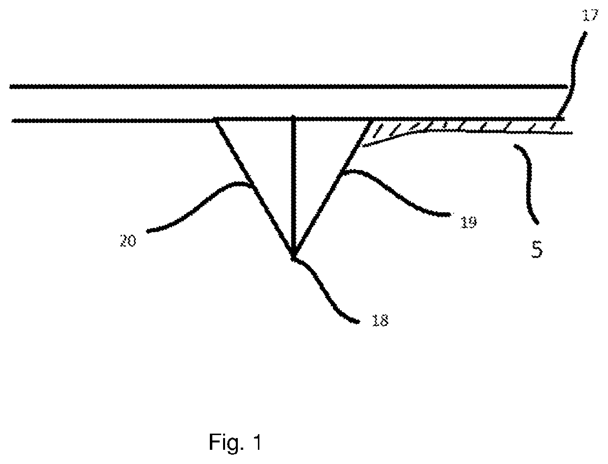
[0035]FIG. 1 shows schematically the structure of the device having a two-component drip edge, which is mounted on the underside of a surface (1) aligned at a right angle to the gravitational force. The two-component drip edge is formed by a first flank (19) and a second flank (20), which meet in the edge (18), which is aligned in the direction of the gravitational force. The first flank (19) is disposed on the side of the surface, which is wetted with liquid (5). The first flank (19) is made of a material having approximately the same surface tension as the wetting liquid (5) or having a greater surface tension than the liquid (5). The second flank (20) is formed by a material having a lower surface tension than the material of which the first flank (19) is formed. The surface tension of the material used for the second flank (20) is advantageously lower than the surface tension of the liquid with which the device comes in contact. The liquid (5) spreads on the surface (17) and the...


PUM


Abstract

The invention relates to a device having a two-component drip edge. One side of the drip edge is formed by a material having an attractive behavior with respect to a liquid and the opposite side of the drip edge is formed from a material having a repulsive behavior with respect to the liquid. This design yields an improved drip effect.

Description

TECHNICAL FIELD[0001]The invention relates to devices with which a controlled drip of liquids is to be guaranteed, as in the case of a pan roller in a printing machine.BACKGROUND[0002]Drip edges are known in the state of the art and are always used in practice whenever a liquid, which wets a surface that is disposed essentially perpendicular to the gravitational force is to be made to drip passively, i.e., driven by the gravitational force, at a certain location in the device in a controlled manner. This should prevent the surface, which is disposed behind the drip edge, from coming in contact with the liquid. Furthermore, the dripping liquid can be collected beneath the drip edge in a targeted manner.[0003]Drip edges are usually mounted on surfaces, which are disposed mostly at a right angle to the direction of the gravitational force, for example, and which are wetted at least temporarily with a liquid which is to be made to drip from this surface in a controlled manner. Drip edge...

Claims


Application Information

Patent Timeline
IPC IPC(8): B41F31/20B41F31/26
CPCB41F31/20B41F31/26B41F31/00B41F31/02
Inventor MEISINGER, SEBASTIAN
Owner FRESENIUS MEDICAL CARE DEUTSCHLAND GMBH
Why Eureka
Try Eureka