

Inductor
a technology of inductors and inductors, which is applied in the direction of transformers/inductance details, inductances with magnetic cores, electrical apparatus, etc., can solve the problems of increasing the signal loss in the high-frequency region, increasing the electrical resistance, and increasing the signal loss, so as to reduce the quality factor (q factor), increase the signal loss, and reduce the inductance
- Summary
- Abstract
- Description
- Claims
- Application Information
AI Technical Summary
Benefits of technology
Problems solved by technology
Method used
Image

Examples
first embodiment
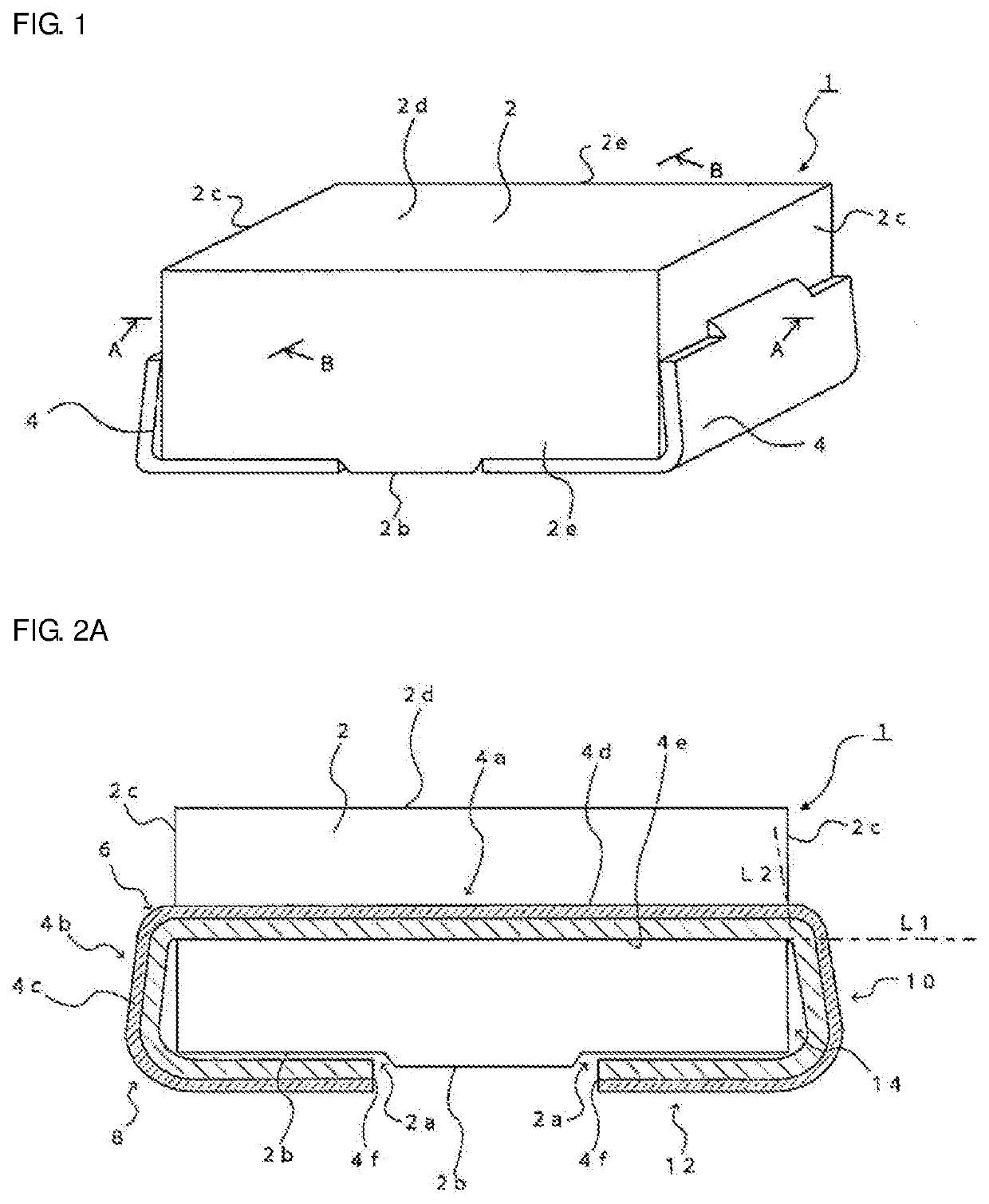
[0026]An inductor 1 according to a first embodiment of the disclosure will first be described below with reference to FIGS. 1 through 3B.
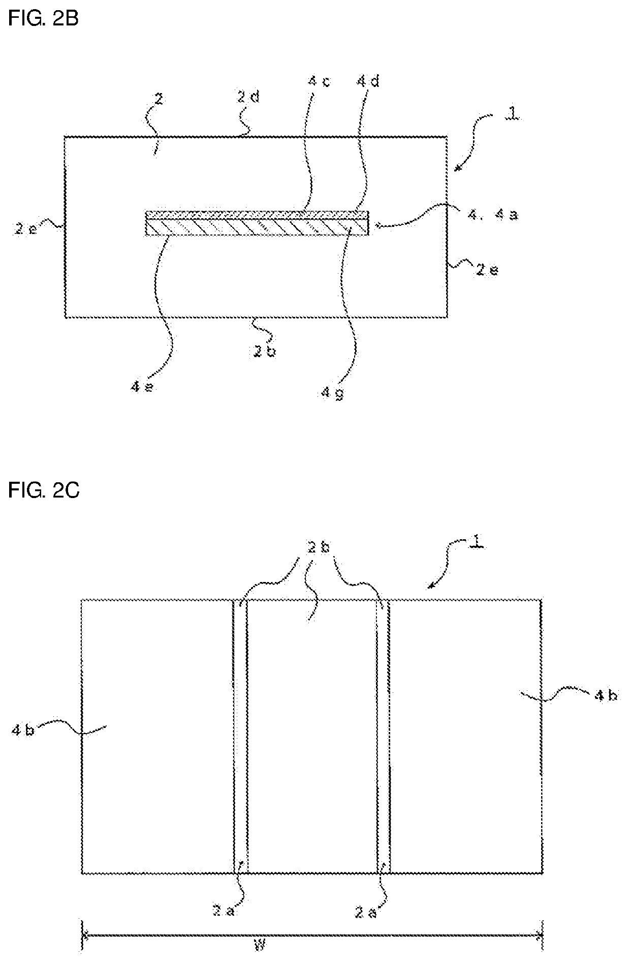
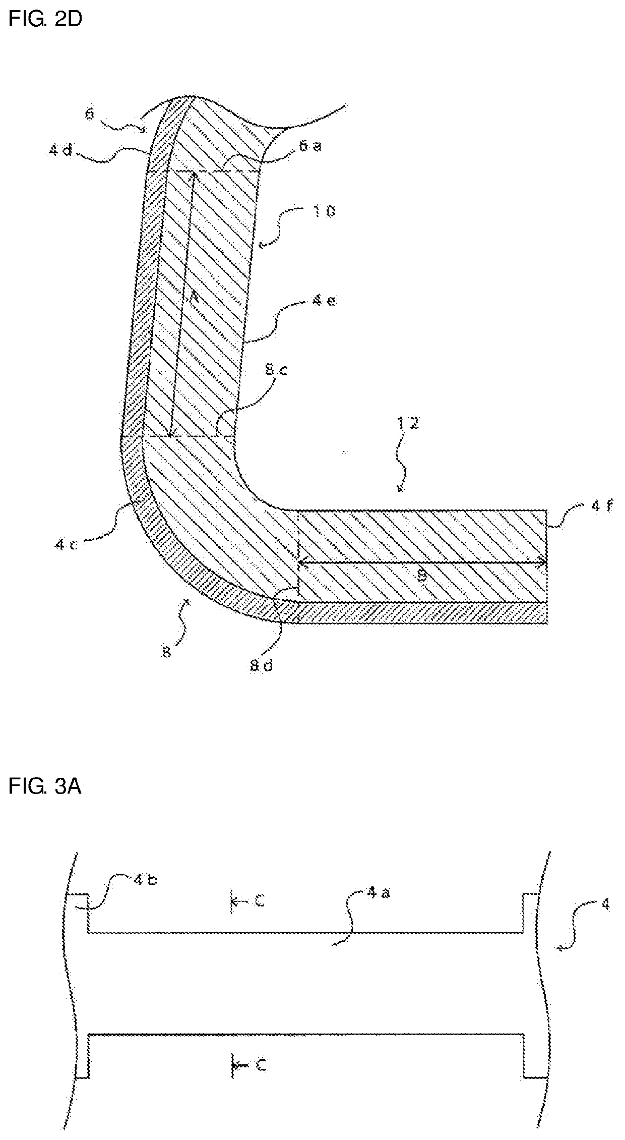
[0027]FIG. 1 is a schematic perspective view of the inductor 1 of the first embodiment. FIG. 2A is a sectional view taken along line A-A in FIG. 1. FIG. 2B is a sectional view taken along line B-B in FIG. 1. FIG. 2C is a bottom view of the inductor 1 shown in FIG. 1. FIG. 2D is an enlarged partial sectional view illustrating the details of a second metal unit 4b in FIG. 2A. FIG. 3A is a plan view illustrating part of a metal body 4 embedded in the inductor 1 in FIG. 1. FIG. 3B is a sectional view taken along line C-C in FIG. 3A.
[0028]The inductor 1 according to the first embodiment, which is a surface mount inductor, includes a base body 2 and a metal body 4. The base body 2 has a bottom surface 2b, a top surface 2d opposing the bottom surface 2b, and two side surfaces 2c and two side surfaces 2e adjacent to the bottom surface 2b and the top surfac...
second embodiment
[0064]An inductor 21 according to a second embodiment of the disclosure will be described below with reference to FIG. 4. FIG. 4 is a schematic sectional view of a first metal unit 24a of the inductor 21 according to the second embodiment. As in FIG. 3B, FIG. 4 illustrates a sectional configuration of the first metal unit 24a in the widthwise direction. The inductor 21 of the second embodiment is different from the inductor 1 of the first embodiment in that the configuration of the first metal unit 24a is different from that of the first metal unit 4a. In FIG. 4, the same elements as those of the inductor 1 are designated by like reference numerals.
[0065](First Metal Unit)
[0066]The first metal unit 24a is constituted by multiple metal plates 20 stacked on each other in the thickness direction. An insulating member 22 is disposed between the metal plates 20 so as to insulate the metal plates 20 from each other. The first metal unit 4a in the first embodiment may be used as each metal...
third embodiment
[0071]An inductor 31 according to a third embodiment of the disclosure will be described below with reference to FIGS. 5A and 5B. FIG. 5A is a schematic plan view of a first metal unit 34a of the inductor 31 according to the third embodiment. FIG. 5B is a schematic sectional view taken along line D-D in FIG. 5A. The inductor 31 of the third embodiment is different from the inductor 1 of the first embodiment in that the configuration of the first metal unit 34a is different from that of the first metal unit 4a. In FIGS. 5A and 5B, the same elements as those of the inductor 1 are designated by like reference numerals.
[0072](First Metal Unit)
[0073]As in the first metal unit 4a in the first embodiment, the first metal unit 34a has substantially a planar shape defined by a length (longitudinal direction) and a width (widthwise direction). The first metal unit 34a is embedded in the base body 2 so that a second surface 34e of the first metal unit 34a becomes substantially parallel with th...
PUM
| Property | Measurement | Unit |
|---|---|---|
| length | aaaaa | aaaaa |
| area | aaaaa | aaaaa |
| length | aaaaa | aaaaa |
Abstract
Description
Claims
Application Information