Broadband over power lines (BPL) coupling system

a technology of power line and coupling system, applied in the direction of power distribution line transmission, transformer/inductance magnetic core, core/yoke, etc., can solve the problem of not having commercially available couplers, and achieve the effect of reducing the probability of sustained fault, preventing power saturation, and less degrading

Inactive Publication Date: 2007-08-02
AMPERION
View PDF7 Cites 17 Cited by
  • Summary
  • Abstract
  • Description
  • Claims
  • Application Information

AI Technical Summary

Benefits of technology

[0010] The design is such that when the unit is clamped in place, a small fixed air gap is established that prevents the core from being saturated by power frequency currents which pass through its window. The coupler's winding structure is designed to accommodate a 1-50 MHz passband requirement. The air gap acts as a barrier to prevent power saturation from the power line. The air gap is a space between the upper (unwound) and lower (wound) half of the ferrite toroid. The size of the gap is controlled by the plastic material which surrounds the two halves of the ferrite. Although this gap is actually filled with plastic, it is still considered an air gap in the jargon with which persons skilled in the art are familiar. This dimension is critical; as the gap increases, the current on the power line has less degrading effect on the magnetics, and therefore, on the signal. As the gap dimension increases, the signal loss also increases, so there is a “sweet spot” at which the immunity to power line current and signal loss are at the most optimal balance.
[0011] The insulated version, primarily for overhead use, includes a multi-element insulation structure that can withstand the power frequency voltage stresses of MV lines. In addition, this coupler structure meets industry standards for impulse voltages with respect to basic impulse insulation BIL, and also for radio influence voltage (RIV). In the event of a line-to-ground failure of the insulation system, the low voltage leads are sized to instantly evaporate, thereby reducing the probability of a sustained fault on the MV system, which therefore reduces associated risk to the public as well as the risk of a resultant circuit outage. The physical design of both insulated and uninsulated couplers is shown in the attached drawings.

Problems solved by technology

In this newly emerging technology, there are no commercially available couplers that meet all the criteria that are essential for such a device to serve its purpose, while safeguarding equipment as well as the general public.

Method used


Image

  • Broadband over power lines (BPL) coupling system
  • Broadband over power lines (BPL) coupling system
  • Broadband over power lines (BPL) coupling system

Examples


Embodiment Construction

[0026] The present invention can be implemented in various different embodiments, and one preferred embodiment will now be described.

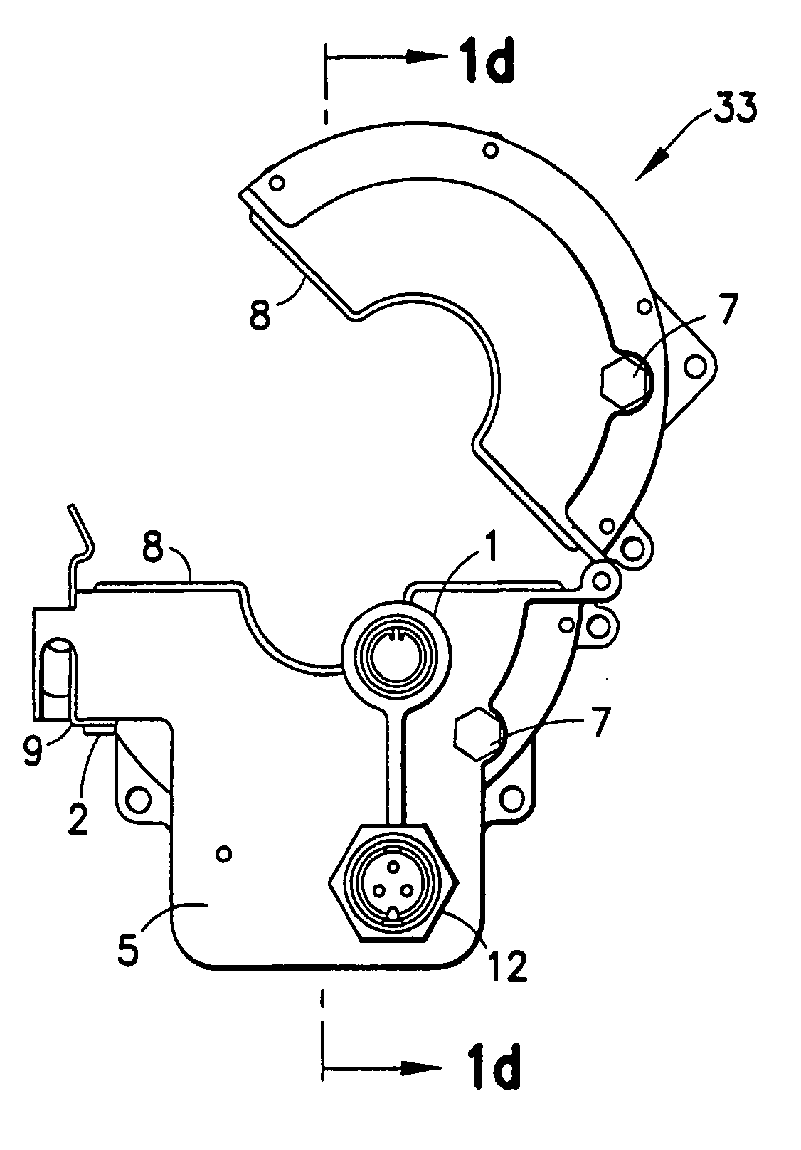
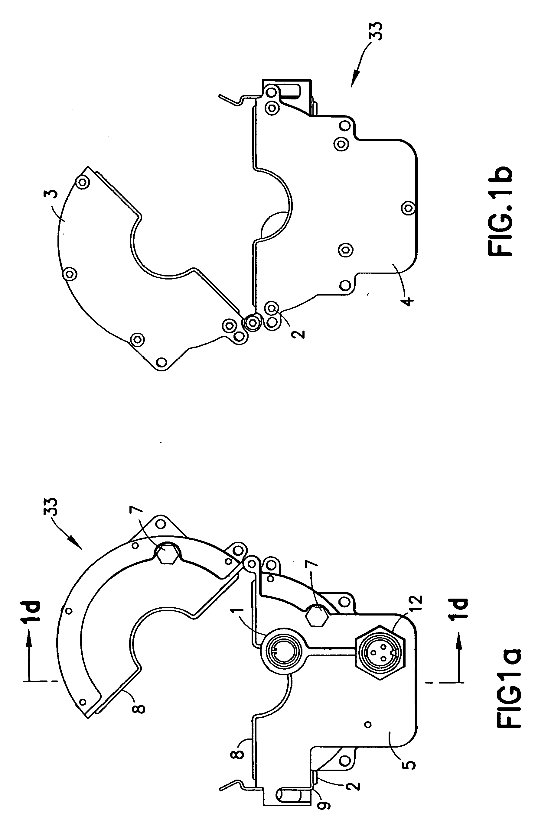
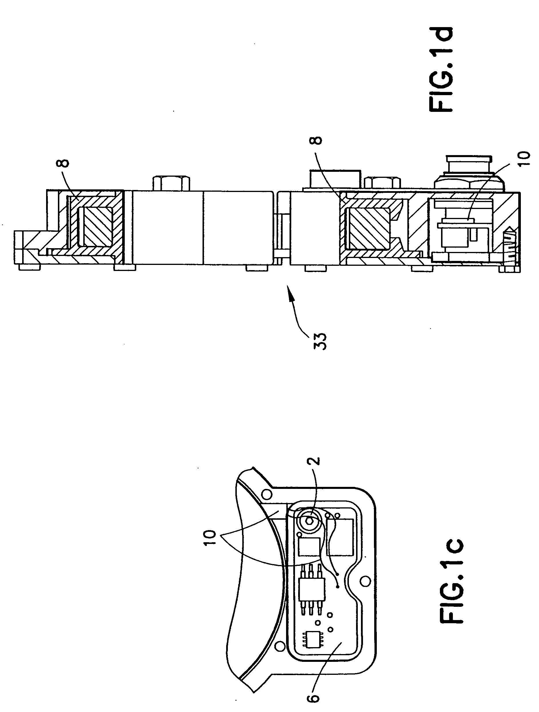
[0027] As shown in FIG. 1(a), a 1.2 inch uninsulated coupler 33 is designed to be placed around the insulation of a jacketed power line. The coupler has two halves held together by a hinge assembly on one side, and a latch 9 and screw 2 on the other side. The coupler includes two portions of a ferrite toroid which is used to couple the signal to the power line. A first portion 10 of the toroid is wound with sixteen turns of magnet wire, while the other portion 13 of the toroid is provided as a magnetic return path to complete the circuit. Also shown in FIG. 1(a) are a connector dust cap 1, and also a thread lock / sealant 12 for plastic fasteners.

[0028] The two portions 10 and 13 of the ferrite toroid are held in place within a metal housing 5, and within the cover pieces 3 and 4 shown in FIG. 1(b). These portions 10 and 13 are held in place by sanopre...


PUM

PropertyMeasurementUnit
frequencyaaaaaaaaaa
frequencyaaaaaaaaaa
flat frequencyaaaaaaaaaa

Abstract

An inductive coupler provides an interface between a power line and a communication device which communicates via the power line. The power line operates at a potential between four and 140 kilovolts while accommodating a current having a frequency between 45 and 65 hertz, and the communication device operates substantially at ground potential. The inductive coupler includes a split ferrite core having material selected to provide a substantially flat frequency response between one and 50 megahertz. The coupler also includes a clamping mechanism allowing the inductive coupler to clamp around the power line or around a utility line connected to the power line. Further, the coupler includes at least one lead for communicatively connecting the inductive coupler to the communication device. The inductive coupler forms an air gap when the inductive coupler is clamped. If the coupler is insulated, the insulation is also used for the air gap.

Description

TECHNICAL FIELD [0001] The present invention relates to communication via power transmission lines, and more particularly to broadband communication via power lines (BPL). BACKGROUND OF THE INVENTION [0002] BPL requires the transfer of high frequency (HF) signals, from communication devices operating at ground potential, to medium voltage (4-35 kV) power lines, and vice versa. Couplers are used for such transfers, and these couplers must accurately inject and extract tiny HF signals while being unaffected by the much larger currents and voltages (having low frequencies on the order of 50 or 60 Hz) that normally exist on medium voltage (MV) power lines. In addition, these couplers must be designed to withstand the transient voltages and currents that occasionally occur on MV lines as a result of switching operations, lightning strikes, electrical faults and other such phenomena. Furthermore, these couplers must be designed to fail in a manner that does not create a safety hazard for ...

Claims


Application Information

Patent Timeline
Patent Type & Authority Applications(United States)
IPC IPC(8): H01F27/26
CPCH01F3/14H04B2203/5483H04B3/56H01F38/14
Inventor RENZ, BRUCE A.LONG, DAVIDSANDAHL, TODD W.
Owner AMPERION
Why Eureka
Try Eureka