
Brake driving control circuit and breakdown detection method thereof

a control circuit and brake technology, applied in the direction of dynamo-electric converter control, program control, motor/generator/converter stopper, etc., can solve the problem of inability to ensure safety, and achieve the effect of ensuring safety without impairing i

Active Publication Date: 2020-10-01
NIPPON DENSAN CORP
View PDF0 Cites 1 Cited by
  • Summary
  • Abstract
  • Description
  • Claims
  • Application Information

AI Technical Summary

Benefits of technology

The present invention is about a brake driving control circuit that can safely use a low voltage to the switch, eliminating the need for a separate power supply. Additionally, the invention provides a reliable method to detect any breakdown of the switches.

Problems solved by technology

When control is performed by only one switch as shown in Patent Literature 1 and the switch breaks down in a short-circuited manner, the brake is always released and there is concern that safety cannot be ensured.

Method used


Image

  • Brake driving control circuit and breakdown detection method thereof
  • Brake driving control circuit and breakdown detection method thereof
  • Brake driving control circuit and breakdown detection method thereof

Examples


Embodiment Construction

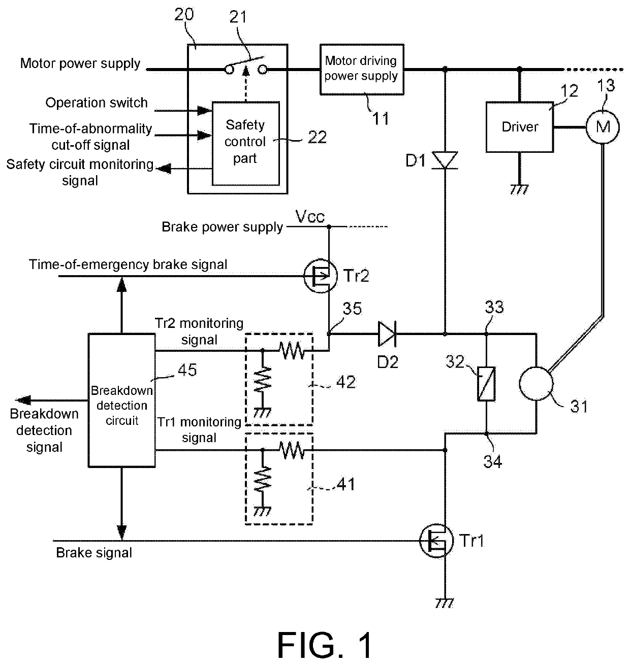
[0026]Next, an embodiment of the present invention will be described with reference to the drawings. FIG. 1 is a diagram illustrating a brake driving control circuit according to an embodiment of the present invention, and illustrates a state in which the brake driving control circuit is incorporated in a robot. A plurality of motors 13 that is servo-controlled by a robot controller is provided in the robot, but a motor 13, an electromagnetic brake 31, and a brake driving control circuit for one shaft of the robot are illustrated in FIG. 1.

[0027]The electromagnetic brake 31 is mechanically connected to a rotating shaft of the motor 13, as indicated by a double line in FIG. 1. A surge absorber 32 for absorbing a large counter electromotive force generated when a current to a solenoid (coil) of the electromagnetic brake 31 is cut off is provided in the solenoid in parallel. As the surge absorber 32, for example, a varistor or a diode is used. A driver 12 is provided in each motor 13 f...


PUM


Abstract

The brake driving control circuit, which controls an electromagnetic brake that releases the brake by applying a current, is provided with: a first rectifying element provided between a first power supply of a first circuit voltage and one terminal of the electromagnetic brake; a cut-off switch inserted into a line through which the first power supply supplies power; a first switching element provided between the other terminal of the electromagnetic brake and a ground point; and a second switching element and a second rectifying element provided in series between a second power supply of a second circuit voltage, which is different from the first circuit voltage, and the one terminal of the electromagnetic brake.

Description

TECHNICAL FIELD[0001]The present invention relates to a brake driving control circuit that controls driving of an electromagnetic brake attached to a motor or the like, and a breakdown detection method thereof.BACKGROUND ART[0002]In a robot, an electromagnetic brake is attached to a motor shaft in order to prevent a robot arm from moving or dropping when the power for a motor driving each shaft is cut off, thereby ensuring safety. In general, an electromagnetic brake provided in a robot is of a non-excitation operation type, and is configured to enter a release state when the electromagnetic brake is energized and to operate when the energization is cut off, that is, lock a motor shaft. Further, an electromagnetic brake provided in a robot is required to be able to release the brake in a state in which a power supply for driving a motor is lost in safety standards (UL 1740, ISO 10218) regarding robots. Patent Literature 1 discloses a device in which a motor brake power supply part f...

Claims


Application Information

Patent Timeline
Patent Type & Authority Applications(United States)
IPC IPC(8): H02P3/08H02M7/06G01R31/34
CPCB25J9/1628H02M7/06G01R31/343H02P3/08F16D66/00B25J9/1674G05B2219/41279B25J19/0004H02P3/025B60T8/885F16D2121/14F16D2121/22B60T2270/414B60T2270/406B25J9/1602B60T8/88F16D2121/24
Inventor ODAGIRI, HIDEYUKI
Owner NIPPON DENSAN CORP
Learn More