Beam hopping synchronization system

a beam hopping and synchronization technology, applied in the direction of radio transmission, electrical equipment, transmission, etc., can solve the problems of inability to implement a continuous change in antenna switching and data transmitted via the uplink may not reach its destination efficiently

Active Publication Date: 2020-10-01
AIRBUS DEFENCE & SPACE
View PDF0 Cites 10 Cited by
  • Summary
  • Abstract
  • Description
  • Claims
  • Application Information

AI Technical Summary

Benefits of technology

[0023]The ground station may further align data frames in the data frame sequence with switching defined by a beam hopping sequence by at least one of adjusting data symbol rate in the data transmission, adjusting data frame start time for the data transmission, inserting or removing pilot signals from data frames.
[0024]Embodiments of the present invention enable a BHS to be changed without losing connectivity between the satellite and ground segments of the communication system. Embodiments of the present invention achieve this synchronisation in a manner which does not require interpretation of a timing signal, by the ground segment, but is based on anticipation of the exact time at which change in BHS occurs at the satellite. Embodiments provide more efficient and more accurate synchronisation between the ground and satellite segments than that which is currently available.

Problems solved by technology

Without this, data transmitted via the uplink may not reach its destination efficiently, as, while it may be uploaded in a particular data frame, the frame itself may not be aligned with the BHS.
The scheme therefore requires removal of a traffic-carrying portion of each data frame to accommodate such synchronisation data, and is thus unable to implement a continuous change in antenna switching because of the time which is required for the acquisition of such synchronisation data and subsequent processing.

Method used


Image

  • Beam hopping synchronization system
  • Beam hopping synchronization system
  • Beam hopping synchronization system

Examples


Embodiment Construction

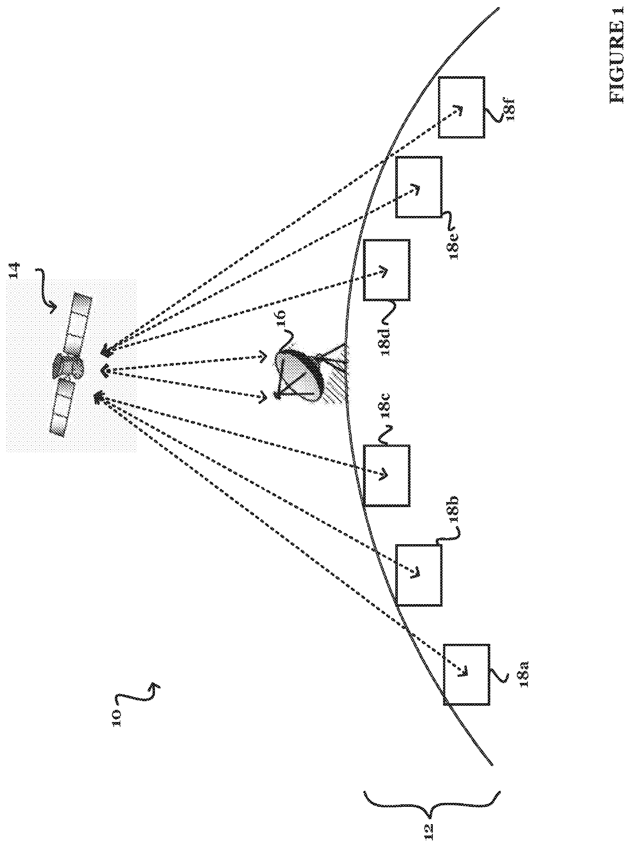
[0032]FIG. 1 illustrates a communication system 10 according to embodiments of the present invention. The communication system 10 comprises a ground segment 12 and a satellite 14. The ground segment 12 contains a gateway 16 referred to herein as a reference gateway, which is illustrated as serving one or more user terminals 18a-f via the satellite 14, although it will be appreciated that there is no restriction on the number of user terminals which can be served. The reference gateway 16 is in communication with the satellite 14 and transmits data to the satellite 14 via an uplink and receives data from the satellite via a downlink.

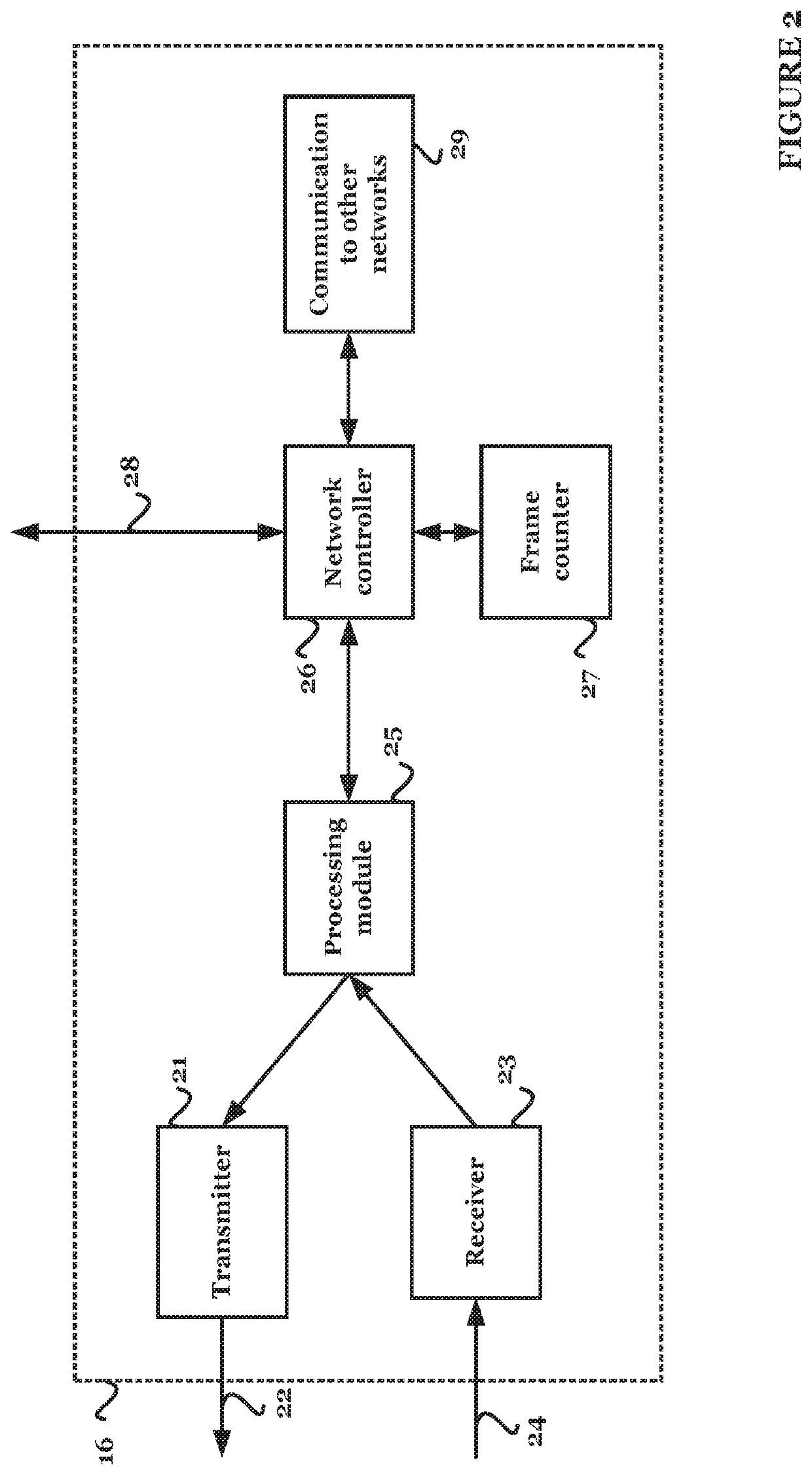
[0033]The reference gateway 16 contains a network controller (not shown) which controls and manages operational functions of the ground segment 12, such as synchronisation of data switching sequences, as described below. In the present embodiments, the network controller also controls and manages operational functions of the satellite 14, to be described ...


PUM


Abstract

Provided are an improved procedure and associated hardware to allow a satellite to switch antenna coverages according to predefined repetitive sequences, and to align switching of the antenna sequence with ground data sequence switching. The disclosed technique enables a beam hopping sequence to be changed without losing connectivity between the satellite and ground segment.

Description

FIELD[0001]The present invention relates to synchronisation between ground and satellite segments of a communication system. Particularly, the present invention relates to the synchronisation of updates to beam coverage sequences employed in the satellite segment of the communications system with data switching employed in the ground segment of the communications system.TECHNICAL BACKGROUND[0002]In a satellite communications system, antenna switching sequences are typically employed in order to maximise throughput, and to optimise use of the available resources. An antenna switching sequence is defined by a set of coverages, representing the geographical area on Earth which is covered by a particular satellite beam transmitted from, or received by the antenna, at a particular time, and a corresponding set of dwell times defining the period of time for which the satellite beam should maintain a particular geographical coverage. On switching, appropriate control of beamforming network...

Claims


Application Information

Patent Timeline
Patent Type & Authority Applications(United States)
IPC IPC(8): H04B7/204H04B7/185
CPCH04B7/18517H04B7/2041H04B7/18515
Inventor LAWS, STEVE
Owner AIRBUS DEFENCE & SPACE
Why Eureka
Try Eureka