Rope gripping member of a hoisting apparatus, rope gripping device, terminal arrangement and hoisting apparatus

a technology of rope gripping and hoisting apparatus, which is applied in the direction of building lifts, elevators, belts/chains/gears, etc., can solve the problems of over-breaking load of load bearing members, and achieve the effect of reducing the likelihood of rope rupture and reducing the stress of the shear

Active Publication Date: 2020-10-22
KONE CORP
View PDF0 Cites 1 Cited by
  • Summary
  • Abstract
  • Description
  • Claims
  • Application Information

AI Technical Summary

Benefits of technology

[0008]It is brought forward a new rope gripping member for a rope gripping device, the rope gripping member comprising an elongated rope gripping face for being pressed against an elongated side face of an end section of a rope, the elongated rope gripping face having a longitudinal direction and a front edge and a rear edge; wherein the tensile stiffness of the rope gripping member in longitudinal direction of the gripping face increases non-linearly with accelerating rate from the front edge towards the rear edge of the gripping face. With this solution one or more of the above mentioned objects are achieved. Particularly, by adjusting stiffness of the gripping member to be as described above, shear stresses can be made more equal over the contact length between the gripping member and the rope. Hereby, particularly existence of very high and thereby harmful shear stresses close to the front edge of the gripping face can be eliminated. Equalized stress distribution reduces likelihood of ruptures of the rope, such as creep related ruptures in particular, but also ruptures caused by local internal stresses within load bearing members of the rope, which may cause exceeding breaking load of the load bearing member in question.

Problems solved by technology

Equalized stress distribution reduces likelihood of ruptures of the rope, such as creep related ruptures in particular, but also ruptures caused by local internal stresses within load bearing members of the rope, which may cause exceeding breaking load of the load bearing member in question.

Method used


Image

  • Rope gripping member of a hoisting apparatus, rope gripping device, terminal arrangement and hoisting apparatus
  • Rope gripping member of a hoisting apparatus, rope gripping device, terminal arrangement and hoisting apparatus
  • Rope gripping member of a hoisting apparatus, rope gripping device, terminal arrangement and hoisting apparatus

Examples


Embodiment Construction

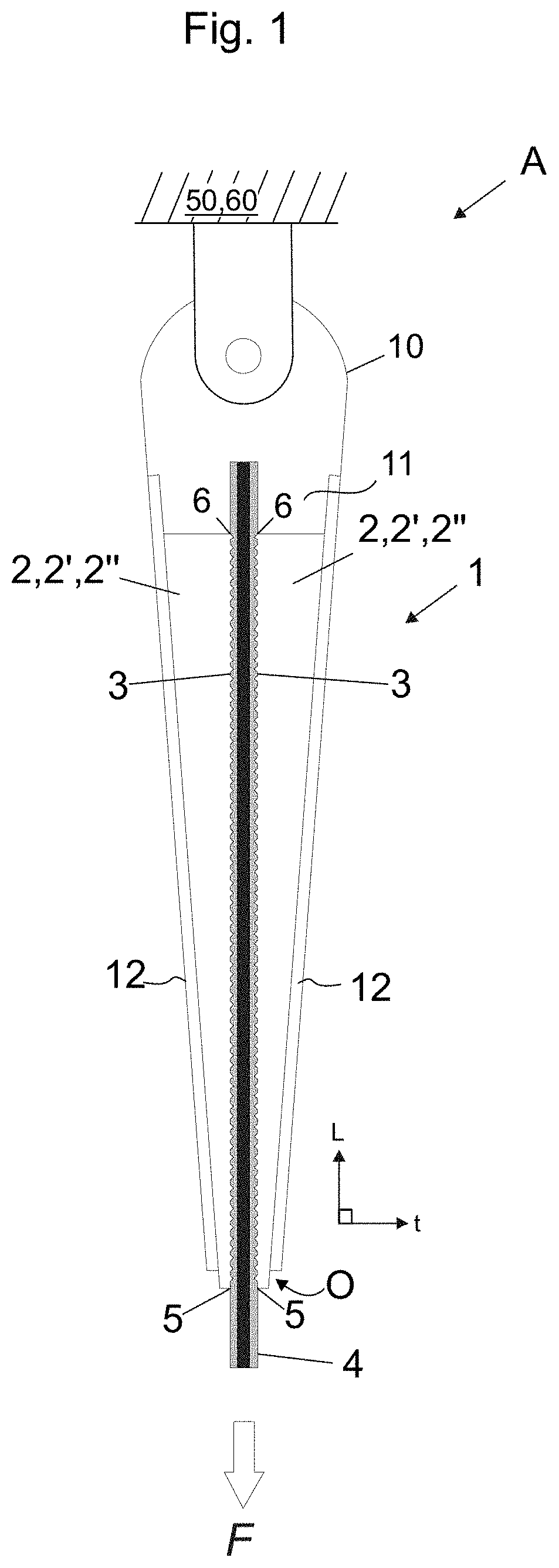
"d_n">[0079]FIG. 1 illustrates a rope terminal arrangement A of a hoisting apparatus comprising a rope gripping device 1, and an elongated rope 4 of a hoisting apparatus. The rope gripping device 1 comprises a frame 10 and two rope gripping members 2.

[0080]Each rope gripping member 2 comprises an elongated rope gripping face 3 for being pressed against an elongated side face 3 of an end section of the rope 4, the elongated rope gripping face 3 having a longitudinal direction L and a front edge 5 and a rear edge 6.

[0081]The two rope gripping members 2 are mounted on the frame 10 such that the rope gripping face 3 of each of them is pressed against an elongated side face of the rope 4.

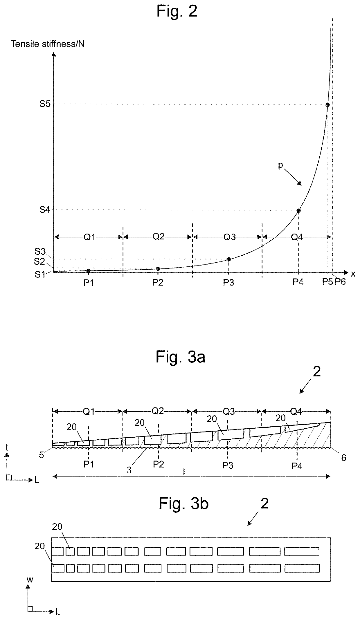
[0082]FIG. 2 illustrates a tensile stiffness-plot of each said rope gripping member 2 as function of x, wherein x is the distance in said longitudinal direction L from the front edge 5 of the gripping face 3, presenting the tensile stiffness of the gripping member 2 in different points P1-P4 along longit...


PUM


Abstract

The invention relates to rope gripping member for a rope gripping device, the rope gripping member comprising an elongated rope gripping face for being pressed against an elongated side face of an end section of a rope, the elongated rope gripping face having a longitudinal direction and a front edge and a rear edge; wherein tensile stiffness of the rope gripping member in longitudinal direction of the gripping face increases non-linearly with accelerating rate from the front edge towards the rear edge of the gripping face. The invention also relates to a rope gripping device, a rope terminal arrangement and a hoisting apparatus implementing the rope gripping member.

Description

RELATED APPLICATIONS[0001]This application claims priority to European Patent Application No. 19169840.6 filed on Apr. 17, 2019, the entire contents of which are incorporated herein by reference.FIELD OF THE INVENTION[0002]The invention relates to gripping a rope of a hoisting apparatus. Said hoisting apparatus is preferably an elevator for vertically transporting passengers and / or goods.BACKGROUND OF THE INVENTION[0003]In hoisting apparatuses, it is typical that one or more ropes are used as the means by which the load to be hoisted is suspended. Each rope end needs to be fixed to a fixing base, which is typically either the load to be lifted or a stationary structure, depending on the type of suspension chosen for the elevator. In elevators, the rope ends can be fixed directly to the load, such as the car or counterweight, which is the case when these are to be suspended with 1:1 ratio. Alternatively, the rope ends can be fixed to a stationary structure of the building, which is t...

Claims


Application Information

Patent Timeline
Patent Type & Authority Applications(United States)
IPC IPC(8): B66B7/08F16G11/04
CPCF16G11/044B66B7/085F16G11/02F16G11/04B66B7/06B66B7/08B66B9/00
Inventor HELENIUS, JUHARENVALL, JANI
Owner KONE CORP
Why Eureka
Try Eureka