End user controlled load management system

a load management system and end user technology, applied in the field of end user controlled load management system, can solve the problems of increasing the complexity of the calculation of real time electric bill, unable to offer real time electric contracts to end users, and difficulty in buying the exact amount of electricity the end user will use, so as to achieve complete flexibility in how they consume electricity, save money, and be palatable

Inactive Publication Date: 2020-10-22
DUNBAR CHRISTOPHER
View PDF0 Cites 1 Cited by
  • Summary
  • Abstract
  • Description
  • Claims
  • Application Information

AI Technical Summary

Benefits of technology

[0018]The system requires no utility, REP, ISO or control authority input, and the end users will make decisions to cut power to their devices to save themselves money. This is one of the key advantages of this system. At no point can a utility, REP, ISO or control authority make any changes to the end user's usage. In other words, the ...

Problems solved by technology

Even with said ‘hedge’ transaction in place it is hard to buy the exact amount of electricity the end user will use, as usage is heavily related to weather and other factors that will not be known in advanced.
As a resul...

Method used


Image

  • End user controlled load management system
  • End user controlled load management system
  • End user controlled load management system

Examples


Embodiment Construction

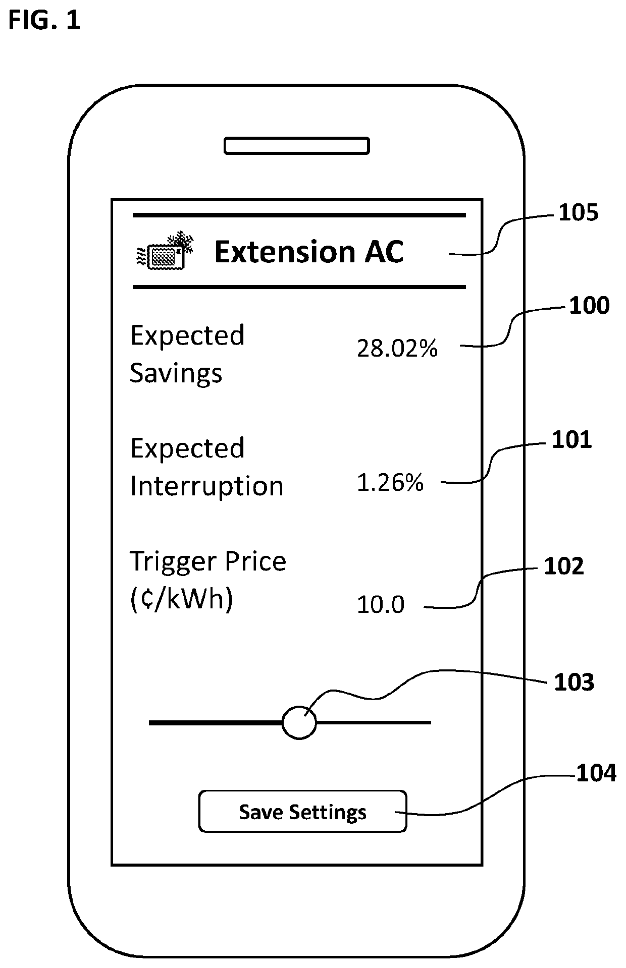
[0034]The present invention is a combination of hardware and software components that interact together allowing an end user to make choices to shut down or reduce power to their high power usage devices. Devices include but are not limited to air conditioning or heating systems, water heaters, pool pumps, electric vehicles or any other high power usage device. The system as described works with both regular devices (devices that are not network or internet connected and controllable through software) and smart devices (devices that are network or internet connected and are controllable through software). The system will operate without the direct involvement of an ISO, REP, or Control Authority. Instead, the end user is enabled through the present invention to make the decision to cut their electricity usage to save money for themselves directly by avoiding usage during high price times.

[0035]The first step in implementing the invention is eliciting the end user's preference for a ...


PUM


Abstract

A control system is disclosed that controls both regular and smart high power usage devices based on real time pricing information. An end user through a user interface sets a trigger price above which the device will shut down or reduce power usage. The control system will operate independently of any system operator or utility and is controlled solely by the end user. A method is disclosed to elicit an end user's preferred trigger price (the price above which to reduce power to the high power usage device). The control system allows end users to override their pre-defined trigger prices to deliver preferable outcomes in response to external and environmental factors. In addition, a method to protect pool equipment from winter freeze events while responding to real time price signals is also disclosed, along with a temperature override device.

Description

RELATED APPLICATIONS[0001]This application claims the benefit of U.S. Provisional Application No. 62 / 588,343, Nov. 18, 2017.BACKGROUND1. Field of Invention[0002]The present application relates generally to systems designed to monitor and regulate the use of electricity in both residential and commercial settings, as well as pricing in retail and wholesale electricity markets.2. Background[0003]Previous solutions for systems designed to monitor and regulate the use of electricity come in many forms that vary in their complexity, but all still have significant limitations.[0004]One of the most basic solutions are time of use programs, where utilities and retail electric providers (REPs) charge end users different rates for using electricity during different times of the day with peak times costing far more than off peak times. The limitation with these programs is that they do not enable or incentivize a specific response at the times when demand and supply on the electric grid are ou...

Claims


Application Information

Patent Timeline
IPC IPC(8): G06F1/3203G06Q50/06G05F1/66G05B19/042
CPCG05B19/0426G06Q50/06G05B2219/2614G06F1/3203G05F1/66G05B2219/2639
Inventor DUNBAR, CHRISTOPHER
Owner DUNBAR CHRISTOPHER
Why Eureka
Try Eureka