
Parameter monitoring and control for an electric driven hydraulic fracking system

a technology of electric drive and hydraulic fracking, which is applied in the direction of positive displacement liquid engine, substation, borehole/well accessories, etc., can solve the problems of limiting the horsepower (hp) that the hydraulic pump may operate, driving up the cost of fracking operation, and adding expense and possible delays

Active Publication Date: 2020-10-29
HALLIBURTON ENERGY SERVICES INC
View PDF0 Cites 127 Cited by
  • Summary
  • Abstract
  • Description
  • Claims
  • Application Information

AI Technical Summary

Benefits of technology

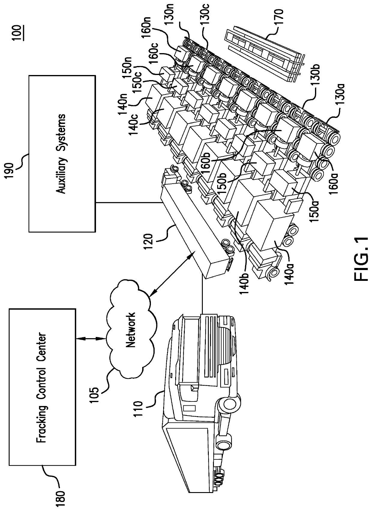
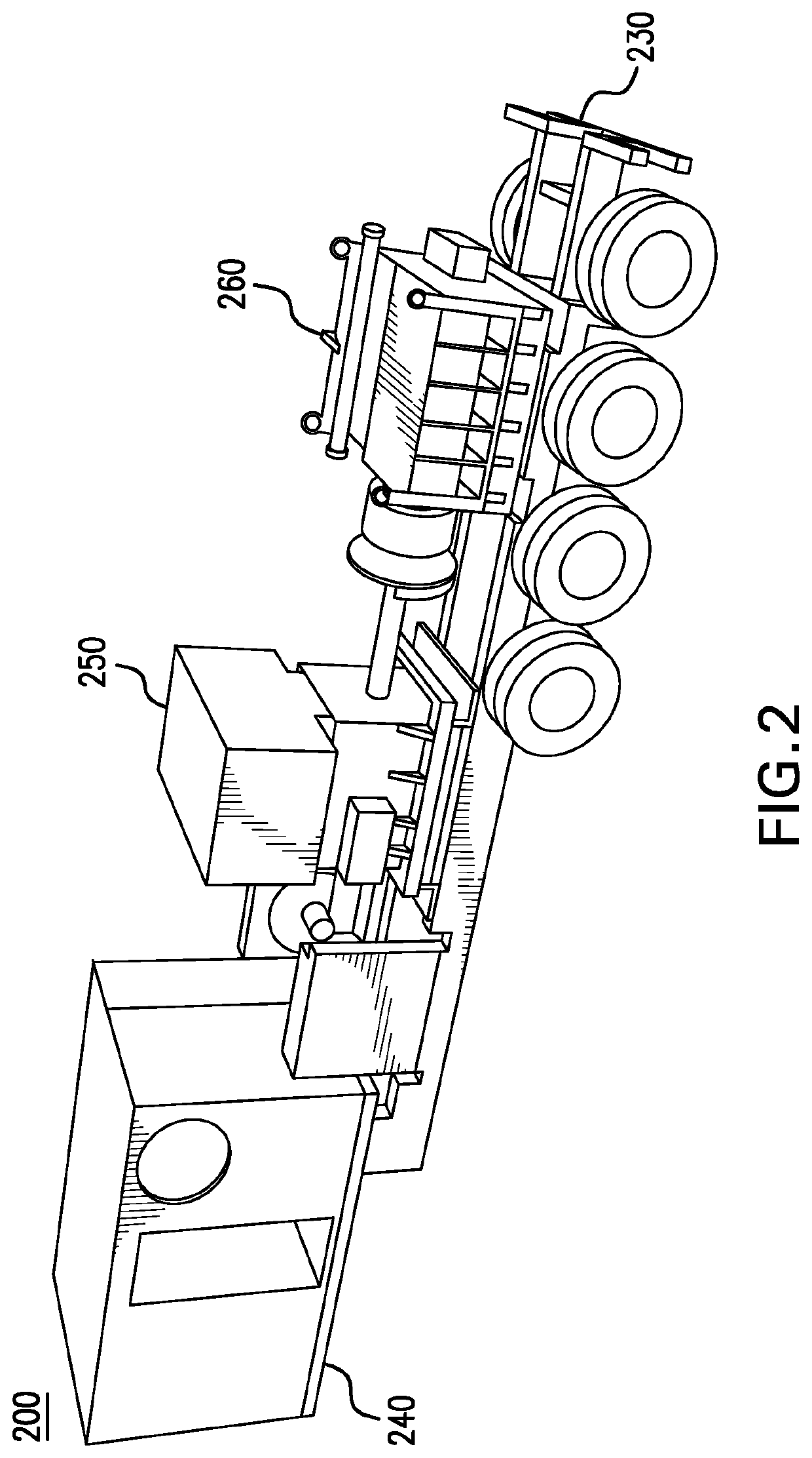
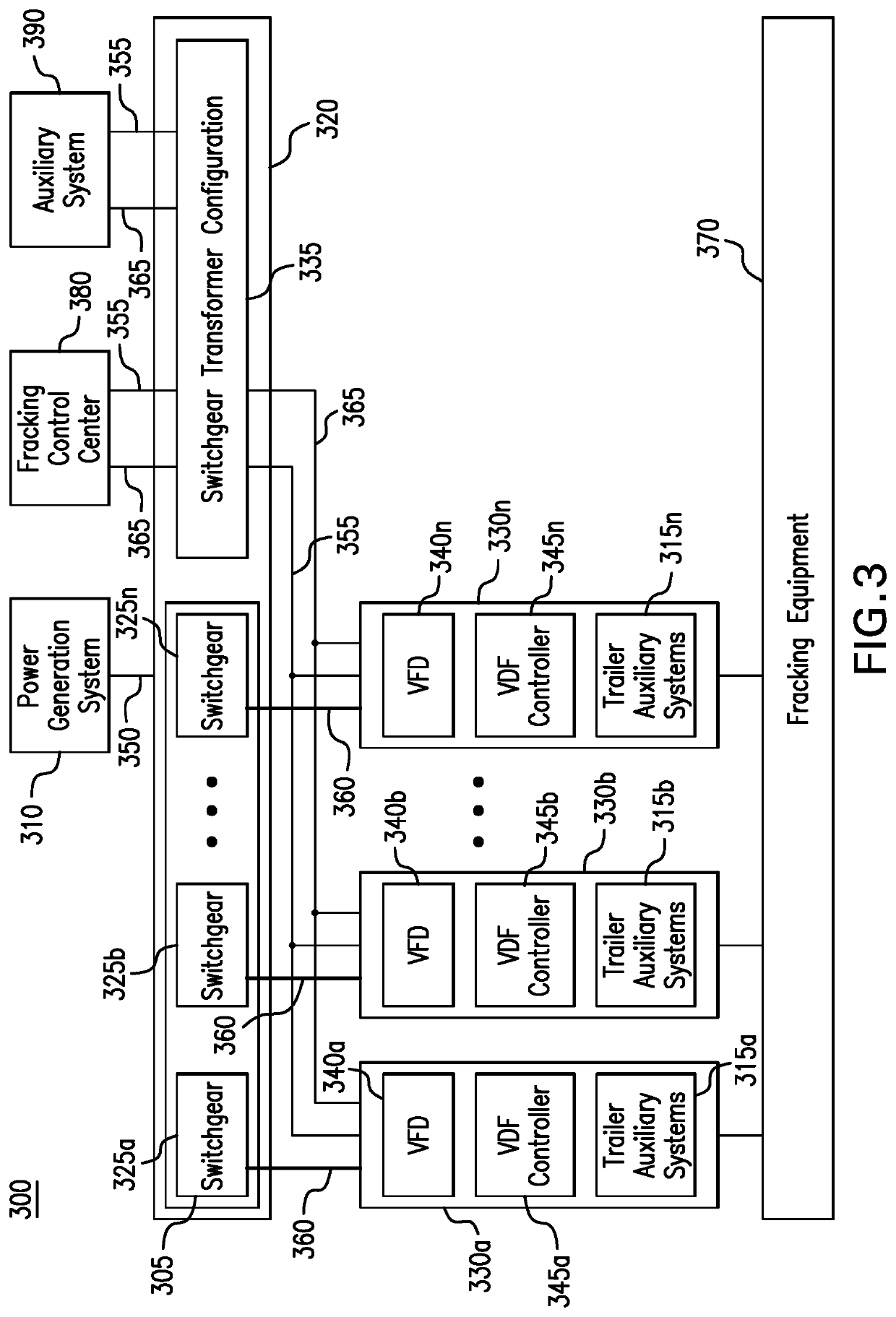
The present patent is about a new electric driven hydraulic fracking system that reduces the cost and complexity of conventional hydraulic fracking systems. The new system uses a single VFD, a single shaft electric motor, and a single hydraulic pump positioned on a single pump trailer. This reduces the number of diesel engines, transmissions, hydraulic pumps, and trailers required at a fracking site, which decreases the cost and complexity of the fracking operation. The new system also improves the productivity and efficiency of the hydraulic pumps by using electric power instead of diesel fuel. The patent also describes the operation of the electric driven hydraulic fracking system and monitors various operation parameters. Overall, the patent provides a technical solution for reducing the cost and complexity of fracking operations.

Problems solved by technology

However, typically several hydraulic pumps are required at a single fracking site to prepare the well for the later extraction of the fluid, such as hydrocarbons, from the existing well.
Typically, the diesel engines limit the horsepower (HP) that the hydraulic pumps may operate thereby requiring an increased quantity of hydraulic pumps to attain the required HP necessary prepare the well for the later extraction of fluid, such as hydrocarbons, from the existing well.
The numerous diesel engines, transmissions, and hydraulic pumps required at a fracking site significantly drives up the cost of the fracking operation.
Each of the numerous trailers required to transport and position configurations require CDL drivers to operate as well as increased manpower to rig the increased assets positioned at the fracking site and may be classified as loads in need of permits, thus adding expense and possible delays.
The amount of diesel fuel required to power the numerous diesel engines to drive the numerous hydraulic pumps required to prepare the well for the later extraction of the fluid, such as hydrocarbons, from the existing well also significantly drives up the cost of the fracking operation.
Further, the parasitic losses typically occur as the diesel engines drive the hydraulic pumps as well as drive the auxiliary systems.
Such parasitic losses actually decrease the amount of HP that is available for the hydraulic pumps operate thereby significantly decreasing the productivity of hydraulic pumps.
In doing so, the duration of the fracking operation is extended resulting in significant increases in the cost of the fracking operation.
The diesel engines also significantly increase the noise levels of the fracking operation and may have difficulty operating within required air quality limits.

Method used


Image

  • Parameter monitoring and control for an electric driven hydraulic fracking system
  • Parameter monitoring and control for an electric driven hydraulic fracking system
  • Parameter monitoring and control for an electric driven hydraulic fracking system

Examples


Embodiment Construction

[0013]The following Detailed Description refers to accompanying drawings to illustrate exemplary embodiments consistent with the present disclosure. References in the Detailed Description to “one exemplary embodiment,” an “exemplary embodiment,” an “example exemplary embodiment,” etc., indicate the exemplary embodiment described may include a particular feature, structure, or characteristic, but every exemplary embodiment may not necessarily include the particular feature, structure, or characteristic. Moreover, such phrases are not necessarily referring to the same exemplary embodiment. Further, when a particular feature, structure, or characteristic may be described in connection with an exemplary embodiment, it is within the knowledge of those skilled in the art(s) to effect such feature, structure, or characteristic in connection with other exemplary embodiments whether or not explicitly described.

[0014]The exemplary embodiments described herein are provided for illustrative pur...


PUM


Abstract

An electric driven hydraulic fracking system is disclosed. A pump configuration includes the single VFD, the single shaft electric motor, and the single hydraulic pump mounted on the single pump trailer. A controller associated with the single VFD and is mounted on the single pump trailer. The controller monitors operation parameters associated with an operation of the electric driven hydraulic fracking system as each component of the electric driven hydraulic fracking system operates to determine whether the operation parameters deviate beyond a corresponding operation parameter threshold. Each of the operation parameters provides an indicator as to an operation status of a corresponding component of the electric driven hydraulic fracking system. The controller initiates corrected actions when each operation parameter deviates beyond the corresponding operation threshold. Initiating the corrected actions when each operation parameter deviates beyond the corresponding operation threshold maintains the operation of the electric driven hydraulic fracking system.

Description

CROSS-REFERENCE TO RELATED APPLICATIONS[0001]The present application is a continuation application of U.S. Nonprovisional application Ser. No. 16 / 791,256 filed on Feb. 14, 2020, which claims the benefit of U.S. Provisional Application No. 62 / 805,521 filed on Feb. 14, 2019, which are incorporated herein by reference in their entirety. This application also incorporates U.S. Nonprovisional application Ser. No. 16 / 790,392 herein by reference in its entirety. This application also incorporates U.S. Nonprovisional application Ser. No. 16 / 790,538. This application also incorporates U.S. Nonprovisional application Ser. No. 16 / 790,581 herein by reference in its entirety.BACKGROUNDField of Disclosure[0002]The present disclosure generally relates to electric driven hydraulic fracking systems and specifically to a single Variable Frequency Drive (VFD), a single shaft electric motor, and a single hydraulic pump positioned on a single pump trailer.Related Art[0003]Conventional hydraulic fracking...

Claims


Application Information

Patent Timeline
Patent Type & Authority Applications(United States)
IPC IPC(8): E21B21/08E21B4/04
CPCE21B4/02E21B4/04E21B21/08F04D13/12F04D13/068F04B17/06F04B47/02F04D15/0088F04D13/02F04D13/06F04D13/0693E21B43/2607H02P5/74F04B17/03F05B2220/706F05B2240/941H02K7/18H02P27/04H02J13/00036H02B1/52H02B5/00E21B43/2605E21B7/022F04D13/0686
Inventor FISCHER, JOHNCROSETTO, JOHN J.KUBRICHT, DAVIDCHEATHAM, RICHARDPOLLACK, JEFFREYLAWMAN, CHADTODD, DAVIDNOLEN, TYLER
Owner HALLIBURTON ENERGY SERVICES INC
Learn More