High pressure hydraulic system comprising a sensor for non-invasive diagnostics

Inactive Publication Date: 2020-10-29
OMT DIGITAL SRL
View PDF0 Cites 0 Cited by
  • Summary
  • Abstract
  • Description
  • Claims
  • Application Information

AI Technical Summary

Benefits of technology

The present invention provides a hydraulic system that can detect the pressure of the fluid inside it in a cost-effective and non-invasive way. This helps to improve the performance and efficiency of the system.

Problems solved by technology

However, due to the small size of this area and the high pressures of the fluid present in the control chamber, it would be necessary to use small sensor elements, which are therefore limited in terms of the loads and deformations they can withstand.
In general, the problem is that it is necessary to manage deformations generated by very high pressures (in the order of thousands of bars) in small spaces.
Therefore, the sensor described in this document is unable to directly detect a signal representative of the pressure in the control chamber.

Method used


Image

  • High pressure hydraulic system comprising a sensor for non-invasive diagnostics
  • High pressure hydraulic system comprising a sensor for non-invasive diagnostics
  • High pressure hydraulic system comprising a sensor for non-invasive diagnostics

Examples


Embodiment Construction

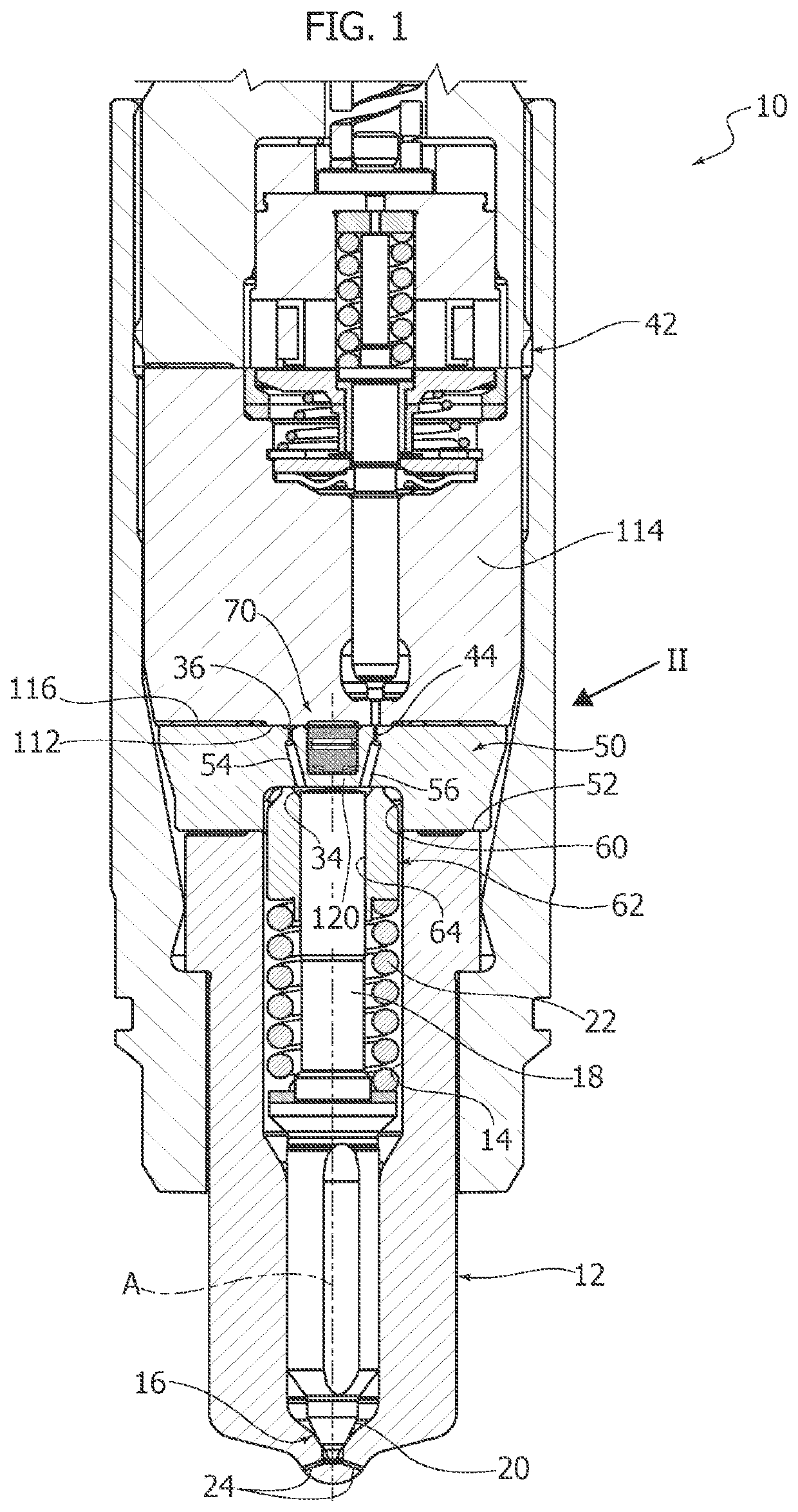
[0020]FIG. 1 illustrates a high pressure hydraulic system. In the example illustrated, the hydraulic system consists of an injector 10 for a common-rail injection system. The injector 10 comprises a pulverizer 12 having a fuel dispensing chamber 14 having a valve seat 16. An injector needle 18 extends into the dispensing chamber 14, and has a sealing surface 20 which cooperates with the valve seat 16. The injector needle 18 is movable along its longitudinal axis A between a closed position in which the sealing surface 20 abuts against the valve seat 16, and an open position in which the sealing surface 20 is spaced apart from the valve seat 16. A spring 22 tends to push the injector needle 18 towards the closed position. The pulverizer 12 has a plurality of injection holes 24 through which the pressurized fuel located in the dispensing chamber 14 is pulverized when the injector needle 18 is in the open position.

[0021]The dispensing chamber 14 is connected to an accumulation volume f...


PUM


Abstract

A high pressure hydraulic system comprising: a hydraulic chamber containing pressurized fluid, a wall which encloses at least one part of the hydraulic chamber and has an integral diaphragm, a piezoelectric sensor isolated from the pressurized fluid contained in the hydraulic chamber by the diaphragm, and an elastic element arranged to apply an elastic force to the piezoelectric sensor, between the piezoelectric sensor and the diaphragm, so that a deformation of the diaphragm produced by a change in the pressure of the fluid contained in the hydraulic chamber causes a change in the elastic force that the elastic element applies to the piezoelectric sensor.

Description

FIELD OF THE INVENTION[0001]The present invention relates in general to high pressure hydraulic systems and regards a high-pressure hydraulic system comprising a sensor for non-invasive diagnostics of the operation of the system.[0002]The invention was developed in particular in view of its application to the diagnostics of fuel injection systems for large diesel and dual-fuel engines, for example, for large naval engines. In the following description, reference will be made to this specific field of use without, however, losing generality.DESCRIPTION OF THE PRIOR ART[0003]In the field of hydraulic systems, and in particular of high pressure injection systems for Diesel engines, there is a growing interest in the development of diagnostic systems capable of acquiring significant data for the diagnostics of operation of complex systems.[0004]This has prompted the development of low-cost sensors that are able to measure characteristic operating parameters, such as hydraulic pressure.[...

Claims


Application Information

Patent Timeline
IPC IPC(8): F02M57/00G01L9/00H01L41/113
CPCF02M2200/247G01L9/008F02M57/005H01L41/1132F02M61/16F02M47/027F02D41/22G01L23/10F02D2041/224F02M65/003F02M2200/21F02M2200/304F02M2200/703G01L1/16H10N30/302
Inventor COPPO, MARCOCATUCCI, FRANCESCOCHIARBONELLO, LORENZOVIOLINO, ANDREA
Owner OMT DIGITAL SRL
Why Eureka
Try Eureka