Device, system and method for detecting body movement of a patient

a technology for detecting body movement and patient, applied in the field of patient body movement detection devices, systems and methods, can solve the problems of complex and computationally expensive motion estimation algorithms, inability to give granular information to the movement detector using these methods, and the accuracy of the used motion estimator is limited, so as to achieve reliable detecting of body movement

Active Publication Date: 2020-10-29
KONINKLJIJKE PHILIPS NV
View PDF0 Cites 1 Cited by
  • Summary
  • Abstract
  • Description
  • Claims
  • Application Information

AI Technical Summary

Benefits of technology

[0010]It is an object of the present invention to provide a device, system and method for reliably detecting body movement in a computationally cheap way and for separating body movements corresponding to different body parts.
[0024]The present invention is based on the idea to provide a device, system and method that allows for reliable yet simple detection and separation of co-occurring motion in a scene. Current motion detection systems are either not able to distinguish between motions occurring at different places in a scene or they may distinguish such motion but only at high expense. Instead of using elaborate motion detection algorithms, the present invention aims to detect body motion, and particularly to distinguish between simultaneously moving body parts, using a simple binary motion / no-motion detection algorithm applied to projection images.
[0026]For an image comprising motion in a first and a second region, for example, the proposed device may generate one or more projection images solely capturing the first region of motion and one or more projection images solely capturing the second region of motion. Combining the different projection images solely capturing the first region of motion while leaving out other projections separates the motion detection signal corresponding to motion in the first region from the motion detection signal corresponding to the second region of motion. Vice versa, combining exclusively projection images solely capturing the second region of motion highlights the motion detection signal corresponding to the second region. Thus, making use of the projection sweep to generate projection images corresponding to different viewpoints, motion detection in said projection images and a combination of the detected motion detection signals allows to separate motion detection signals belonging to movement in different image regions. Accordingly, since different regions of motion belong to different body parts of the patient, movements of different body parts can be detected and analyzed separately. That is, movements of a particular body part can be accurately and independently analyzed even in the presence of co-occurring movements.
[0027]In general, the number of viewpoints directly influences the resolution or granularity with which motion is detected and localized in a scene. That applies all the more so, the more different the projection images are. The more projection images are generated and the smaller the overlapping regions of said projection images are, the finer becomes the granularity of motion detection in a scene. Therefore, a large number of small steps in projection sweep covering a wide range of viewpoints gives the flexibility to segregate even complex body movement into separate projection images. In particular, this method allows to distinguish a large number of co-occurring body movements. Advantageously, to get a meaningful movement analysis, a minimum of three at least partially different projection images is required. Further advantageously, a projection image is tied to a single predefined body part. For example, a first projection image may represent a patient's head, while a second and a third projection image may represent a patient's left and right arm, respectively. This limitation simplifies detecting co-occurring motion even more.
[0032]Correlation based methods, on the other hand, make use of the 2D or 3D correlation coefficient, in particular Pearson's correlation coefficient, of consecutive image frames. This coefficient is defined as the sum over the mean-subtracted pixel-wise intensity multiplications normalized by the intensity variation of pixels or voxels in each frame. Again, high values of the negation of the correlation coefficient, e.g. of (1—correlation coefficient), are considered to be produced by motion. Based upon a predefined threshold for the correlation coefficient and / or the frame difference value the motion detection unit may thus indicate if motion is detected or not in an image. Both the frame differencing and the correlation based method are simple and thus computationally cheap.
[0039]According to another embodiment of the device, the projection sweep unit is configured to obtain images from different angles and / or different zoom levels. This additional information may be used to generate further projection images and thus helps achieve finer granularity. A projection at different zoom levels, for example, helps focus on a moving region to get more detailed information about co-occurring body parts there. This is particularly relevant for the analysis of small body parts moving such as fingers, for example.

Problems solved by technology

A movement detector using these methods can, per se, not give granular information like the location of movement or robust inference on occurrence of a particular movement type.
However motion estimation algorithms are complex and computationally costly to run, and the final inference on motion region / type is limited by the accuracy of the used motion estimator.
This is due to the fact that said algorithms are prone to noise due to their fine granularity, i.e. high resolution, in particular with respect to the kind of video recordings obtained in a clinical setting.
Noisy motion estimations, however, make it very difficult to segregate co-occurring motion in different body parts.
Although spatial segmentation of motion vectors in different clusters may be used to distinguish particularly co-occurring movements, said method is highly complex and non-trivial.

Method used


Image

  • Device, system and method for detecting body movement of a patient
  • Device, system and method for detecting body movement of a patient
  • Device, system and method for detecting body movement of a patient

Examples


Embodiment Construction

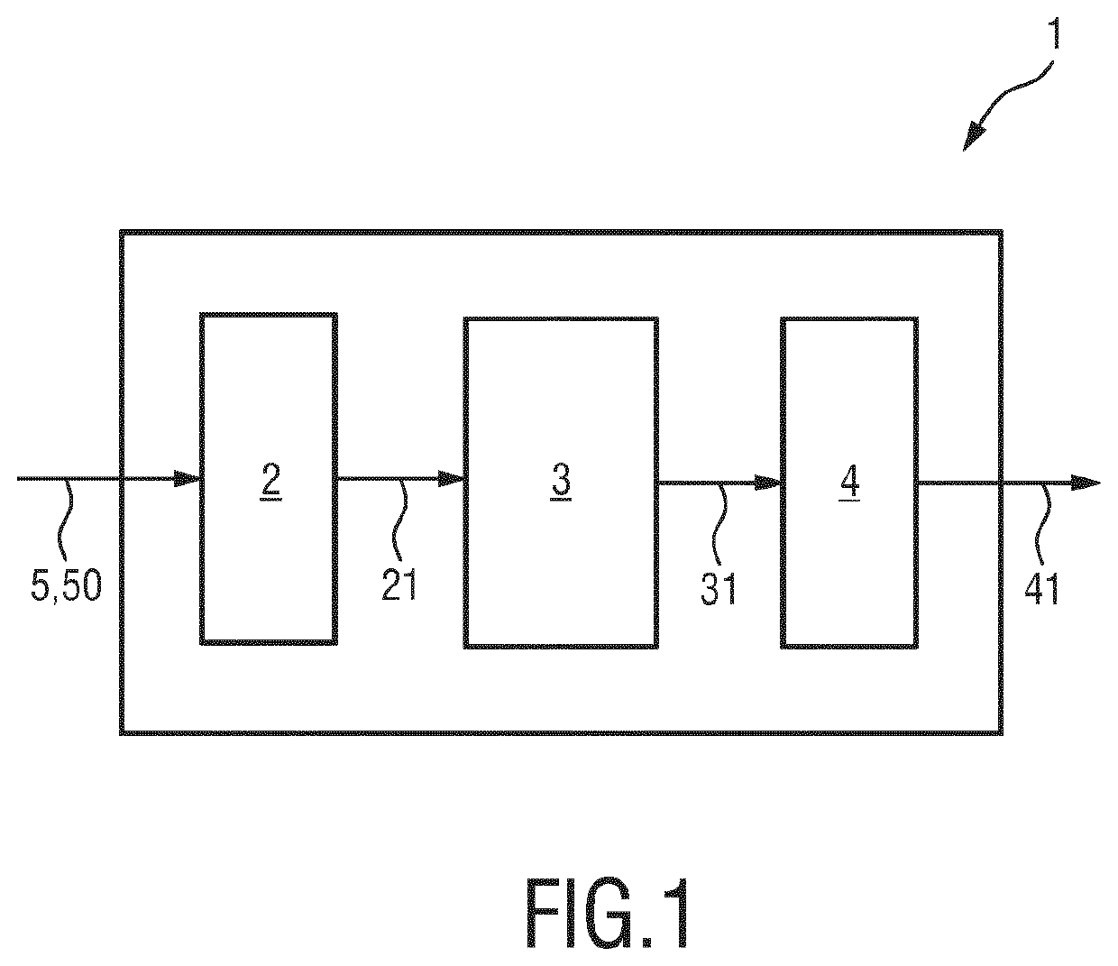
[0055]FIG. 1 shows a schematic diagram of an embodiment of the device 1 for detecting body movement of a patient according to the present invention. The device 1 comprises a projection sweep unit 2, a motion detection unit 3 and an analysis unit 4.

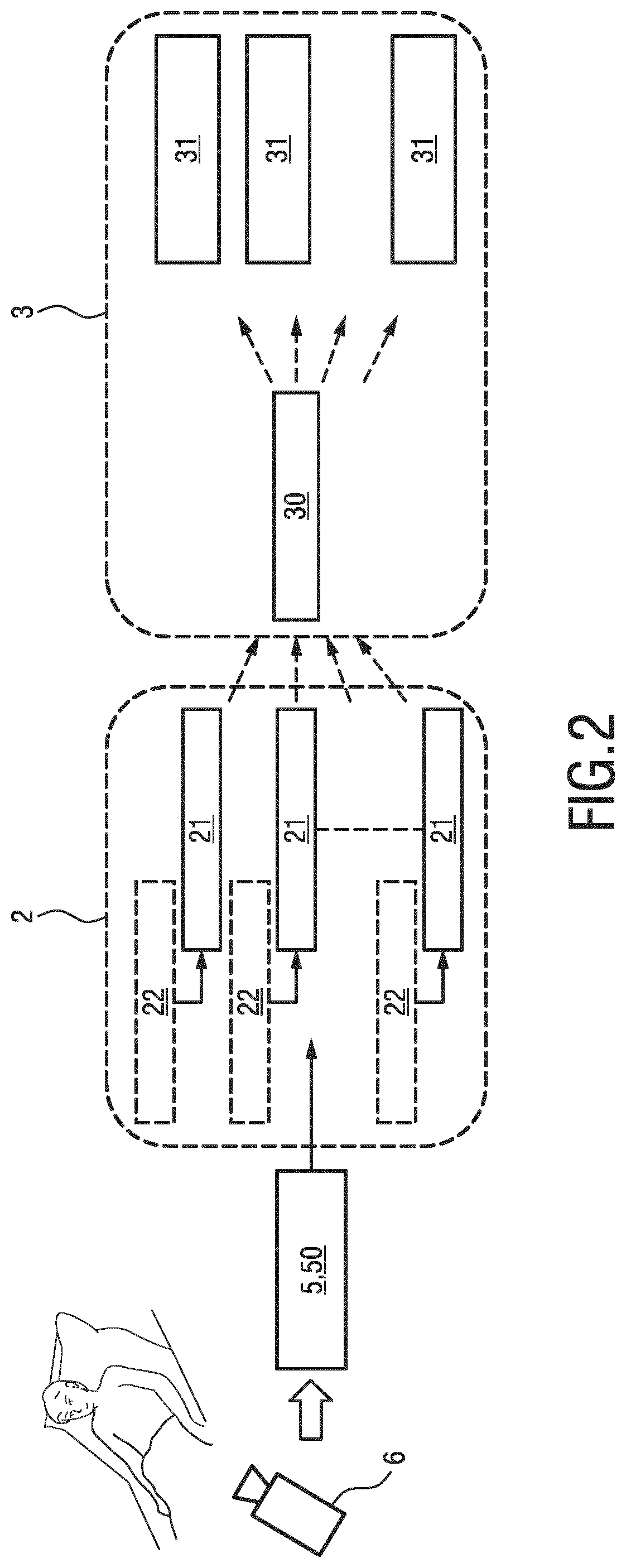
[0056]Using image data comprising depth information 5 the projection sweep unit 2 projects a corresponding image 50 for different viewpoints as if the camera was panned and / or localized elsewhere in the room. Consequently, one or more projection images 21 are obtained. For each of these projection images 21, i.e. the corresponding projection image data, the motion detection unit 3 is configured to detect as a binary decision if motion is present in a respective projection image 21 or not. The motion detection signals 31 thus obtained for the projection images 21 are passed on to the analysis unit 3. In the analysis unit the signals 31 may be combined in any way to detect body movements in the scene in more detail, in particular to localize...


PUM


Abstract

The present invention relates to a device for detecting motion of a person. The present invention further relates to a system incorporating the aforementioned device and a corresponding method. The proposed device comprises a projection sweep unit configured to obtain image data comprising depth information corresponding to an image showing the patient and to generate one or more projection images of the patient for different viewpoints, a motion detection unit configured to detect motion of the patient in the one or more projection images and to generate one or more motion detection signals indicating if motion is detected or not in a respective projection image, and an analysis unit configured to detect and localize body movements of one or more body parts of the patient based on one or more combinations of motion detection signals.

Description

FIELD OF THE INVENTION[0001]The present invention is related to a device for detecting, localizing and analyzing motion of a person. The present invention further relates to a system incorporating the aforementioned device and a corresponding method.BACKGROUND OF THE INVENTION[0002]Automatic detection and analysis of patient movements enable continuous monitoring of patients in hospital or under homecare. Detection and analysis of body motion has a wide spectrum of applications, ranging from athletic performance analysis, surveillance in security-sensitive areas and man-machine interfaces to various clinical applications, like the determination of bed-fall risks. Further application of motion analysis is given by delirium detection. Patients with delirium, for example, exhibit distinct movement patterns with typical movements like floccillation, carphology etc. Hence, when undesirable movement from a patient is seen indicating a particular medical condition such as delirium, doctors...

Claims


Application Information

Patent Timeline
Patent Type & Authority Applications(United States)
IPC IPC(8): G06T7/20G06T7/00G06T7/50
CPCG06T2207/20081G06T7/20G06T2207/30004G06T2207/30196G06T2200/24G06T7/50G06T7/0012G06T2207/10028G06T7/254
Inventor LAMICHHANE, BISHALFERNANDO, SHAKITH DEVINDAHEINRICH, ADRIENNEVAN DER HEIDE, ESTHER MARJANFALCK, THOMAS MARIA
Owner KONINKLJIJKE PHILIPS NV
Why Eureka
Try Eureka