
Telescoping Flush Handle for Lift and Slide Doors

a technology for sliding doors and handles, applied in the field of sliding doors, can solve problems such as occupying valuable living space, creating aesthetic problems, and being able to bypass

Active Publication Date: 2020-11-05
RENNER ROBERT
View PDF0 Cites 2 Cited by
  • Summary
  • Abstract
  • Description
  • Claims
  • Application Information

AI Technical Summary

Benefits of technology

The present disclosure provides a telescoping handle that can be mounted flush to a door stile and can be extended for better leverage when lifting heavy doors. The handle has a minimal footprint within the door and does not cause damage to the door frame or other door panels. Additionally, the spindle can be scored to indicate length points for trimming to accommodate different door thicknesses.

Problems solved by technology

One significant limitation associated with this type of handle is its protruding nature, which creates certain disadvantages.
For example, the handle is not hidden from view, so it creates aesthetic issues.
In addition, when multiple panels in a lift and slide door system roll parallel to another, the protruding handle on the door's stile prohibits the same doors to bypass one another.
This limitation of not being able to bypass one another requires a deeper wall cavity for storage when the panels are nested in a wall cavity.
Consequently, the deeper wall cavity takes up valuable living space in this arrangement.
In addition, the protruding handles prevent the door panels from lining up flush with each other causing a displeasing stepped appearance to the entire door system.
However, this creates other problems, such as requiring an additional step to remove the handle and then reattach the handle when the door is to be moved.
Furthermore, the inconvenience associated with attaching and removing the handle may be further complicated if the handle is misplaced or lost, which is not only time-consuming but expensive if the handle must be replaced.
Moreover, removable handles can be accidentally dropped when assembling or disassembling causing damage to the floor and / or the user.

Method used


Image

  • Telescoping Flush Handle for Lift and Slide Doors
  • Telescoping Flush Handle for Lift and Slide Doors
  • Telescoping Flush Handle for Lift and Slide Doors

Examples


Embodiment Construction

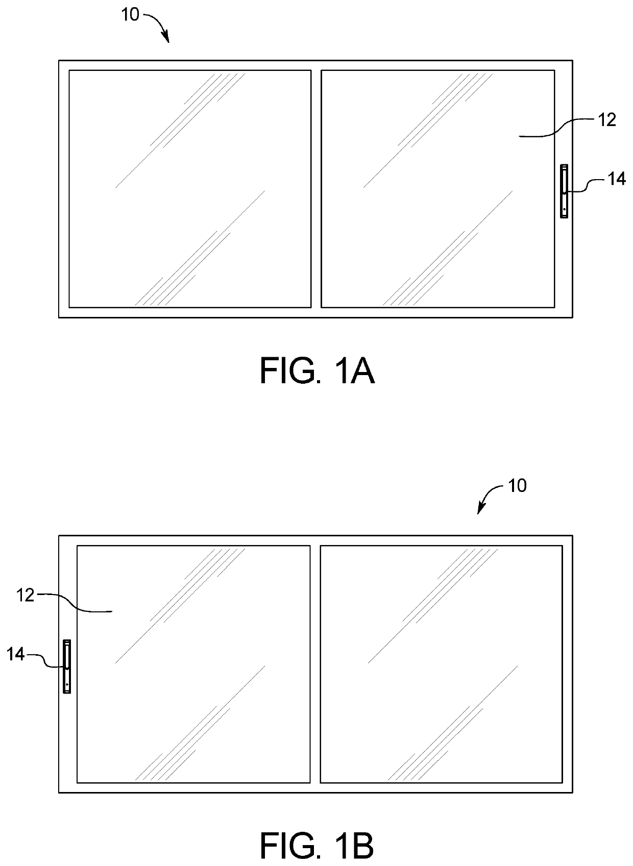
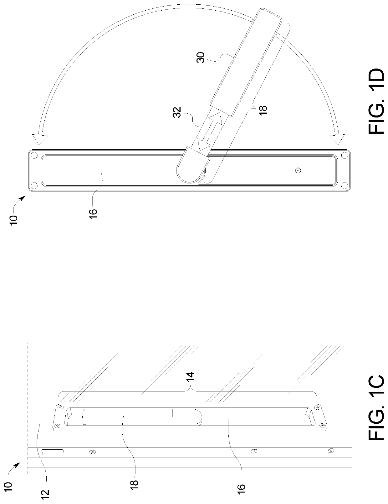
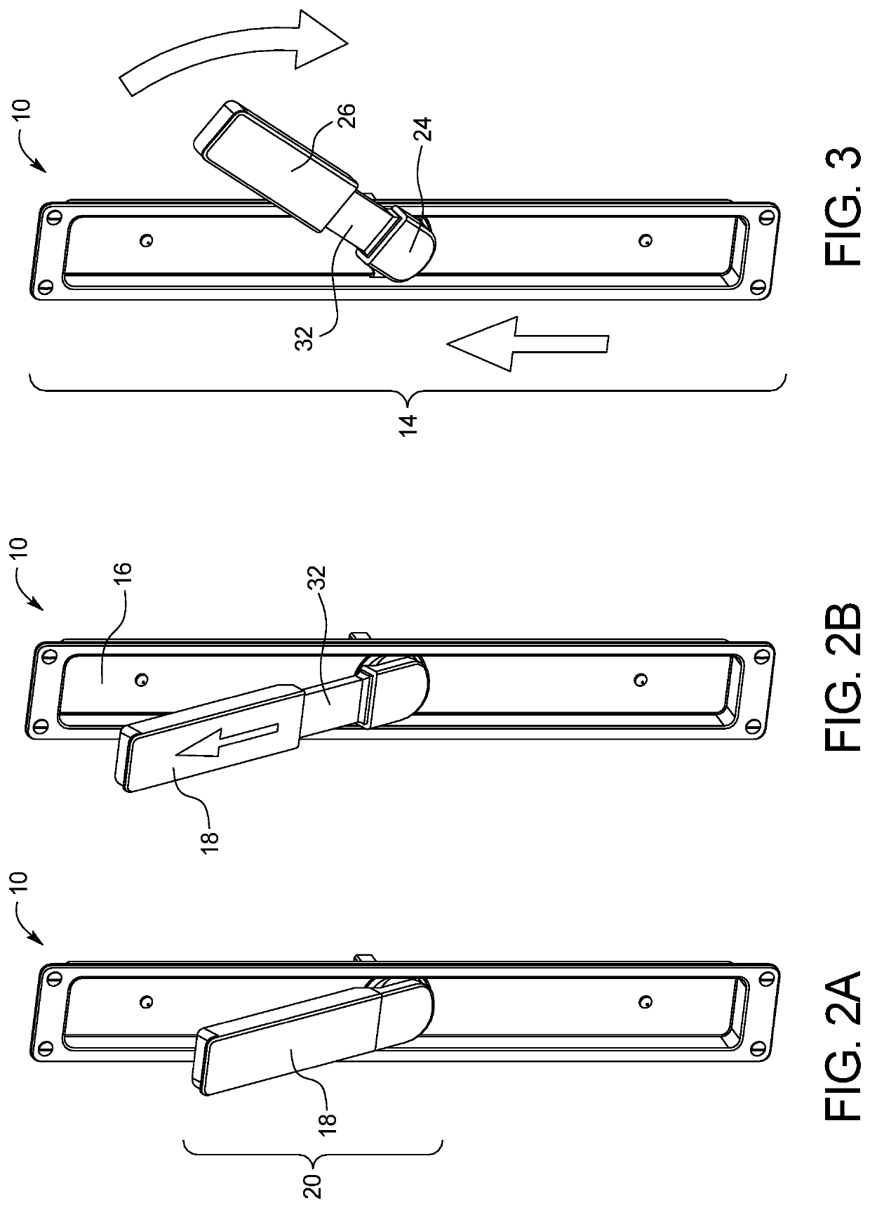
[0026]The present disclosure includes a handle assembly system for use with lift and slide doors. The handle assembly can include a handle housing that can serve as a support frame for housing and securing the handle flush within a front face of the door. The handle can be pivoted out of the handle housing and extended to increase length, wherein rotating the handle allows a user to actuate the door panels in order to open and close the sliding door system. The telescoping handle can allow a user to grip the handle and provide a lever-type function to reduce the force required by the user to actuate the panel, such as to lift the panel onto or off (e.g., up or down) the track. Specifically, the rotation actuates a typical mechanism in the lift and slide door panel to raise the panel off the ground and move a bearing system in contact with an exposed bead of a track in the floor. The user can then use the handle and apply force in the direction he or she desires the door to be moved....


PUM


Abstract

The present disclosure includes a handle assembly system for use with lift and slide doors. The handle assembly can include a handle housing that can serve as a support frame for housing and securing the handle flush within a front face of the door. The handle can be pivoted out of the handle housing and extended to increase length, wherein rotating the handle allows a user to actuate the door panels in order to open and close the sliding door system. The telescoping handle can allow a user to grip the handle and provide a lever-type function to reduce the force required by the user to actuate the panel, such as to lift the panel onto or off the track.

Description

CROSS-REFERENCE TO RELATED APPLICATIONS[0001]This application incorporates by reference and claims the benefit of priority to U.S. Provisional Application 62 / 665,675 filed on May 2, 2018.BACKGROUND OF THE INVENTION[0002]The present subject matter relates generally to sliding doors and, more particularly, to a telescoping handle that may be stored substantially flush with a door adapted to lift and slide such that the handle is out of the way while still being connected to the door.[0003]A lift and slide door operates similar to a standard sliding door except it utilizes a roller system that allows the door panels to be lifted vertically above a track, so that the panels roll smoothly and quietly for opening and closing. As a result, a lift and slide door can efficiently divide and / or unify interior spaces of a house with exterior spaces of the house. A lift and slide door can also be utilized to divide interior spaces, replace traditional garage doors, among other applications.[0004...

Claims


Application Information

Patent Timeline
IPC IPC(8): E05B1/00E05B65/08
CPCE05B65/0876E05B1/003E05Y2900/132E05B1/0053E05B1/0092E05B65/08E05B5/003Y10T292/57E05B85/107E05B85/16E05B85/103E05B85/14E05B85/10Y10S292/31Y10T292/28E05B5/006E05B83/40Y10T292/089
Inventor RENNER, ROBERTROBERTS, JIMGRIEP, JOHNASHFORD, JEFF
Owner RENNER ROBERT
Learn More