
Fiber Optic System For Detecting Forces On And Measuring Deformation Of An Anthropomorphic Test Device

a fiber optic system and test device technology, applied in the field of anthropomorphic test devices, can solve the problems of difficult estimation of the position or shape of individual parts of the atd, difficult monitoring of simulated soft organs, and inability to monitor tests in this way

Active Publication Date: 2020-11-05
HUMANETICS INNOVATIVE SOLUTIONS
View PDF0 Cites 0 Cited by
  • Summary
  • Abstract
  • Description
  • Claims
  • Application Information

AI Technical Summary

Benefits of technology

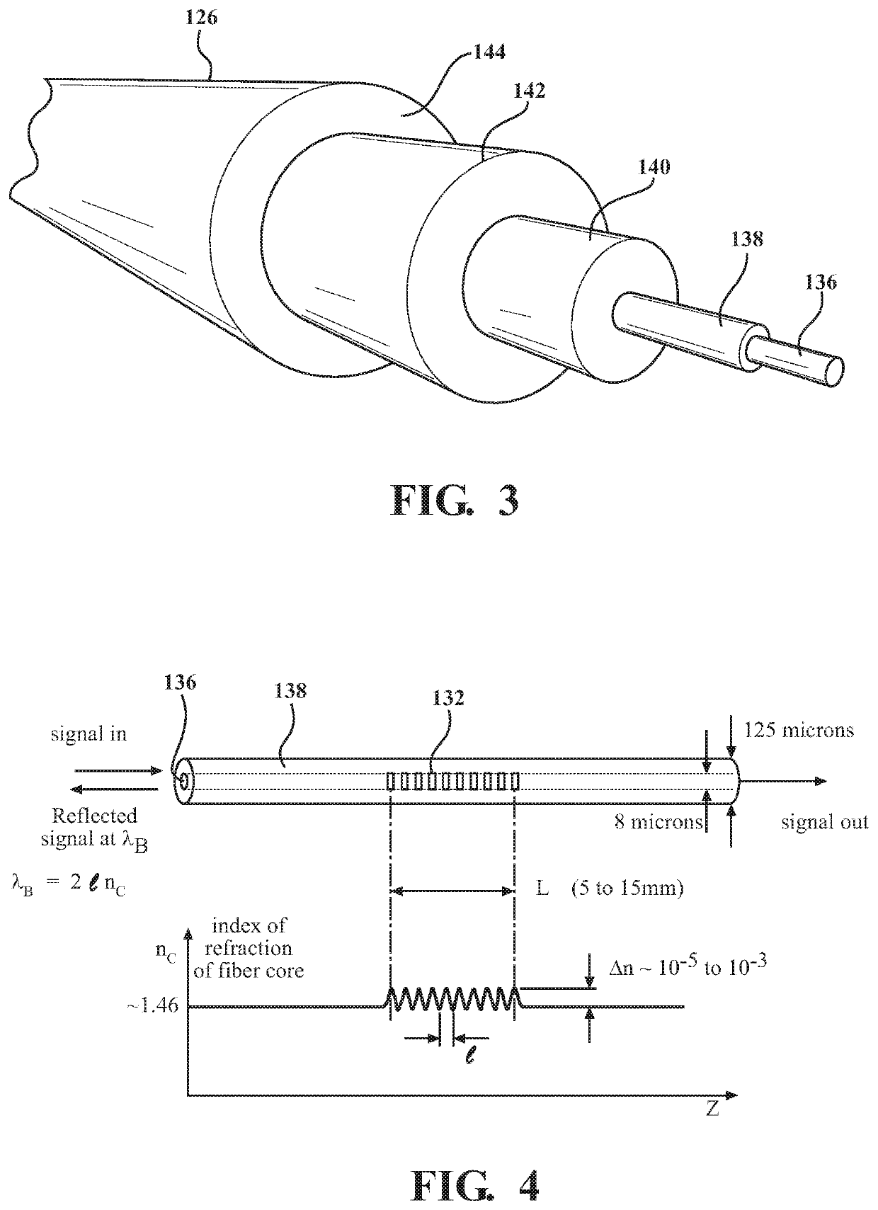
The new fiber optic measurement system can measure stress, strain, and deformation of skeletal structures, organs, and flesh for the ATD to form components, which can vary in structure, material, and shape all at the same time. It can increase biofidelity of all ATDs in use today and in the future. It can also better predict possible injury by allowing for easier evaluation of vehicle restraints. The optical fibers are capable of being threaded through the metal structure to provide a complete analysis of the forces acting on the ATD. Overall, the invention provides accurate and real-time measurements of force distribution.

Problems solved by technology

However, some tests cannot be monitored in this way because of the construction of the structure surrounding the ATD, the presence of other devices, or the inflation of air bags.
Also, the position or shape of individual parts of the ATD may be difficult to estimate, such as limbs and internal organs.
Simulated soft organs are particularly difficult to monitor using traditional strain gauges where it is difficult to measure strain of low Young modulus materials using high Young modulus sensing elements.
These systems are time consuming to set-up and only represent certain aspect of the human body when subjected to forces.
Existing measurement systems rely on individual load cells placed within the ATD and the metal structure of the ATD inhibits the ability to take measurements with such load cells.

Method used


Image

  • Fiber Optic System For Detecting Forces On And Measuring Deformation Of An Anthropomorphic Test Device
  • Fiber Optic System For Detecting Forces On And Measuring Deformation Of An Anthropomorphic Test Device
  • Fiber Optic System For Detecting Forces On And Measuring Deformation Of An Anthropomorphic Test Device

Examples


Embodiment Construction

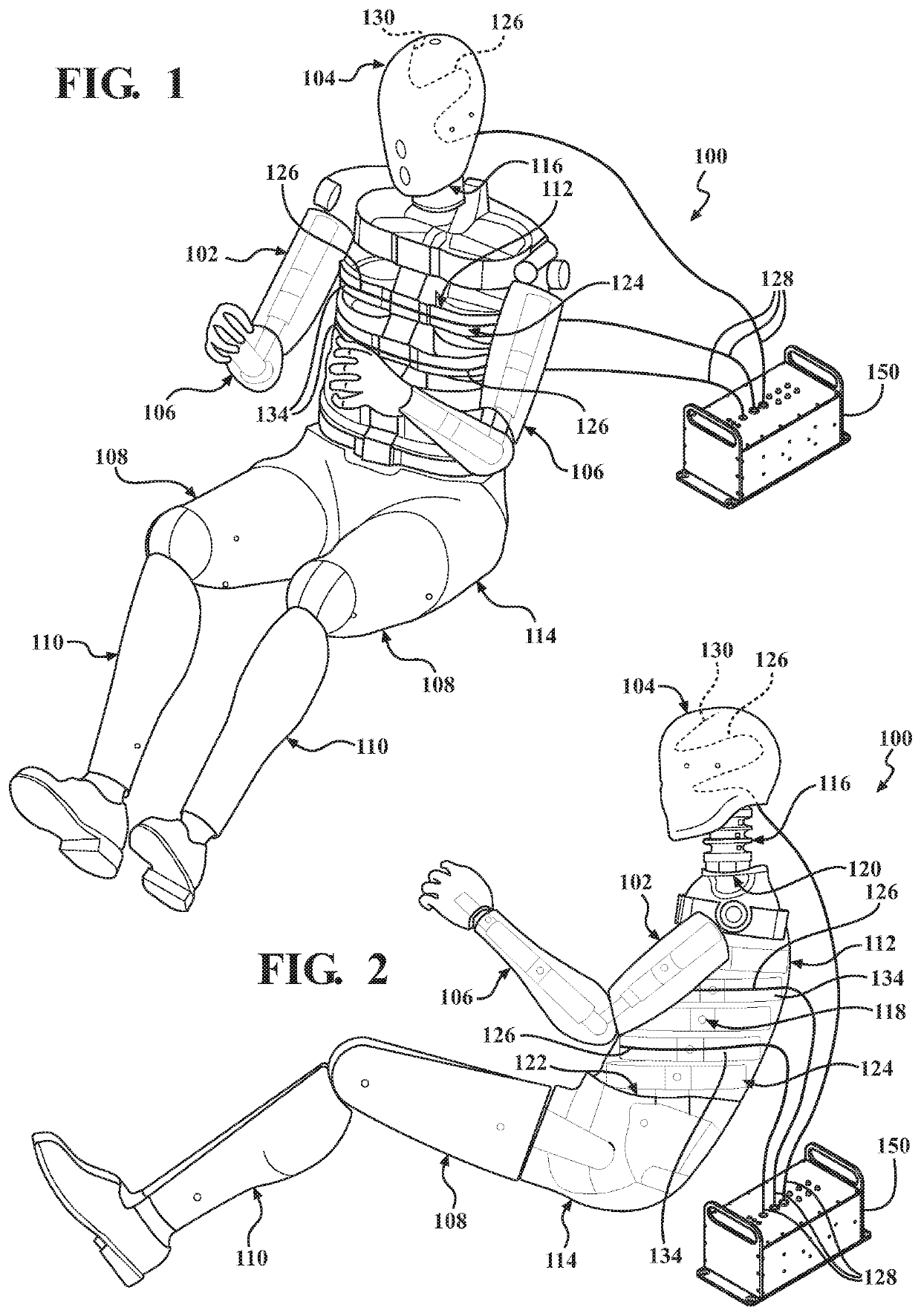
[0035]Referring to the drawings and in particular FIGS. 1 and 2, one embodiment of a system 100 for measuring and detecting forces on an anthropomorphic test device 102, according to the present invention, is shown. The ATD 102, in the example shown, is of a fiftieth percentile (50%) male type and is illustrated in a sitting position. It should be appreciated that the subject invention would apply to all types and sizes of ATDs 102.

[0036]In one embodiment, the ATD 102 is used primarily to test the performance of automotive interiors and restraint systems 100 for adult front and rear seat occupants. The size and weight of the ATD 102 are based on anthropometric studies, which are typically done separately by the following organizations, University of Michigan Transportation Research Institute (UMTRI), U.S. Military Anthropometry Survey (ANSUR), and Civilian American and European Surface Anthropometry Resource (CESAR). It should be appreciated that ranges of motions, centers of gravit...


PUM


Abstract

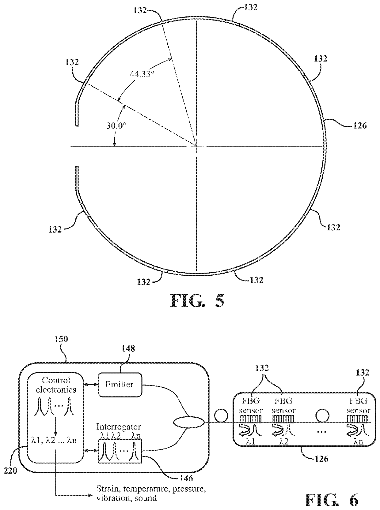
A system for detecting forces on and measuring deformation of an anthropomorphic test device (ATD) includes a plurality of body parts and at least one optical fiber supported by and in contact with at least one of the body parts. The body parts form the ATD and simulate at least a part of a human body and the articulation of the human body. The optical fiber extends between a first end and a second end and comprises a plurality of sensors disposed between the ends. An emitter is in communication with the optical fiber for emitting a light having a predetermined band of wavelengths through the optical fiber that is reflected by the sensors and an interrogator is in communication with the optical fiber for detecting the reflected light from the sensor such that changes to the reflected light indicate a strain on the at least one body part.

Description

RELATED APPLICATIONS[0001]This application claims priority to U.S. Provisional Patent Application No. 62 / 621,388, filed on Jan. 24, 2018, which is hereby incorporated by reference.BACKGROUND1. Field of the Invention[0002]The present invention relates generally to anthropomorphic test devices and, more particularly, to a fiber optic system for detecting forces on and measuring deformation of an anthropomorphic test device.2. Description of the Related Art[0003]Automotive, aviation, and other vehicle manufacturers conduct a wide variety of collision testing to measure the effects of a collision on a vehicle and its occupants. Through collision testing, a vehicle manufacturer gains valuable information that can be used to improve the vehicle.[0004]Collision testing often involves the use of anthropomorphic test devices (ATD), commonly referred to as “crash test dummies.” During collision testing, the ATD is placed inside a vehicle and the vehicle undergoes a simulated collision (sled t...

Claims


Application Information

Patent Timeline
IPC IPC(8): G01L1/24G01L5/00G09B23/32
CPCG01L5/0052G01L1/246G09B23/32G01B11/18
Inventor VARA, THOMAS MATHEWUBOM, IME VICTORBEEBE, MICHAEL SCOTTMCCARTHY, CHARLES JOSEPHBURLEIGH, MARK JOHNDAVIS, JAMESLIPMYER, ROBERT
Owner HUMANETICS INNOVATIVE SOLUTIONS
Learn More