
Low latency management of processor core wait state

Active Publication Date: 2020-11-12
IBM CORP
View PDF0 Cites 2 Cited by
  • Summary
  • Abstract
  • Description
  • Claims
  • Application Information

AI Technical Summary

Benefits of technology

The present disclosure aims to reduce communication between a processor core and a lower level cache when managing the availability of a lock or other variable. This is achieved by supporting the use of per-thread wait flags, which helps to manage thread wait states within the processor core and reduce latency and bandwidth consumption.

Problems solved by technology

This communication increases latency and consumes some of the limited bandwidth of the request communication paths coupling the processor core and the lower level cache(s).

Method used


Image

  • Low latency management of processor core wait state
  • Low latency management of processor core wait state
  • Low latency management of processor core wait state

Examples


Embodiment Construction

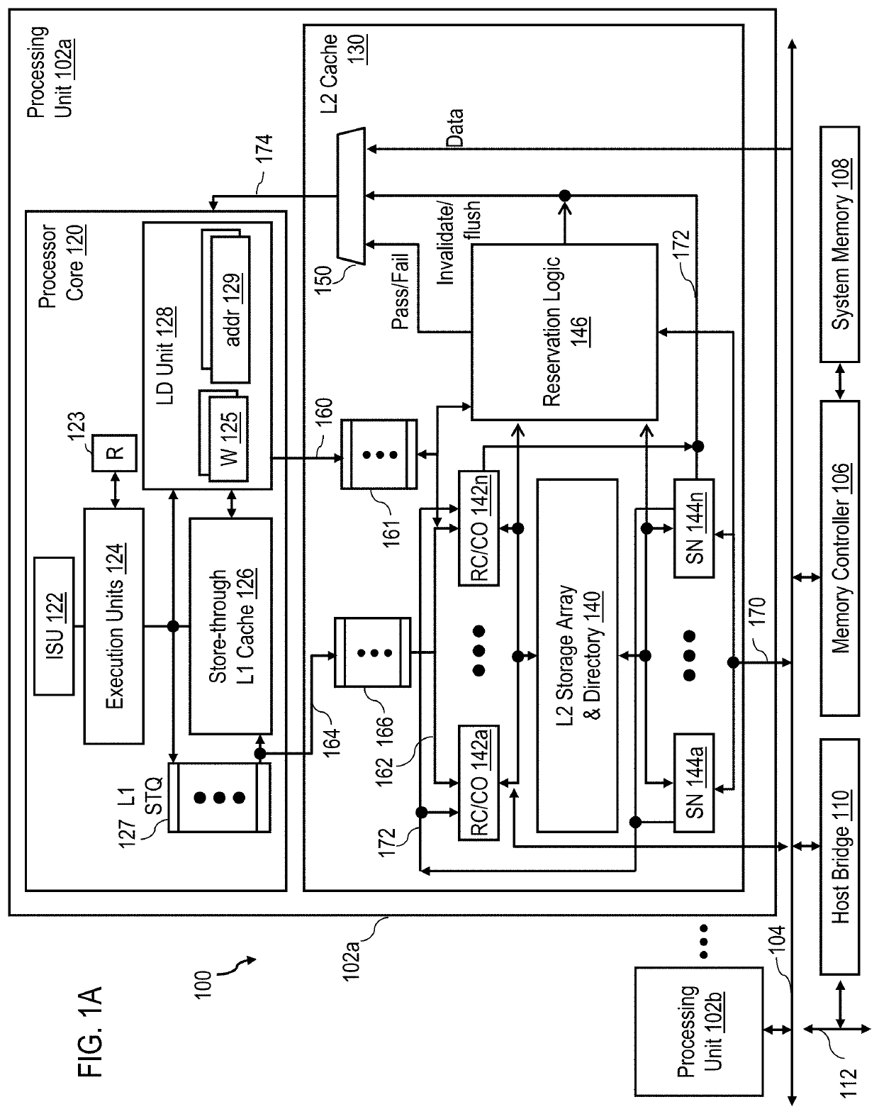
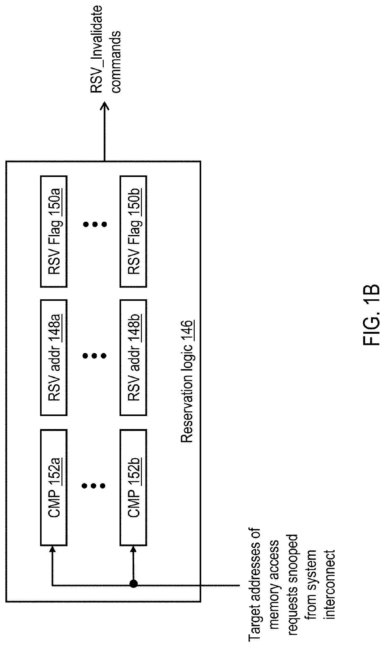
[0024]With reference now to the figures and in particular with reference to FIG. 1A, there is illustrated a high level block diagram of a data processing system 100 in accordance with one embodiment. As shown, data processing system 100 includes multiple processing units 102 (including at least processing units 102a-102b) for processing data and instructions. Processing units 102 are coupled for communication to a system interconnect 104 for conveying address, data and control information between attached devices. In the depicted embodiment, these attached devices include not only processing units 102, but also a memory controller 106 providing an interface to a shared system memory 108 and one or more host bridges 110, each providing an interface to a respective mezzanine bus 112. Mezzanine bus 112 in turn provides slots for the attachment of additional unillustrated devices, which may include network interface cards, I / O adapters, non-volatile memory, non-volatile storage device a...


PUM


Abstract

A data processing system includes multiple processing units all having access to a shared memory. A processing unit includes a lower level cache memory and a processor core coupled to the lower level cache memory. The processor core includes an execution unit for executing instructions in a plurality of simultaneous hardware threads, an upper level cache memory, and a plurality of wait flags each associated with a respective one of the plurality of simultaneous hardware threads. The processor core is configured to set a wait flag among the plurality of wait flags to indicate the associated hardware thread is in a wait state in which the hardware thread suspends instruction execution and to exit the wait state based on the wait flag being reset.

Description

BACKGROUND OF THE INVENTION[0001]The present invention relates in general to data processing system and, in particular, to managing accesses to data in shared memory of a data processing system. Still more particularly, the present invention relates to a processor, data processing system and method providing low latency management of a wait state of a hardware thread in a processor core.[0002]In shared memory multiprocessor (MP) data processing systems, each hardware thread of the multiple processors in the system may access and modify data stored in the shared memory. In order to synchronize access to a particular granule of memory (e.g., a lock or other variable) between multiple processing units and hardware threads of execution, load-reserve and store-conditional instruction pairs are often employed. For example, load-reserve and store-conditional instructions have been implemented in the POWER® instruction set architecture with request codes (opcodes) associated with various mn...

Claims


Application Information

Patent Timeline
IPC IPC(8): G06F9/48G06F12/0811G06F12/0831G06F9/30G06F12/0891G06F9/52
CPCG06F12/0831G06F12/0891G06F9/52G06F12/0811G06F9/4887G06F9/30098G06F9/30043G06F9/30087G06F9/3009G06F9/3851G06F9/526G06F12/0897Y02D10/00
Inventor WILLIAMS, DEREK E.SHEN, HUGHGUTHRIE, GUY L.
Owner IBM CORP
Learn More