

Spark plug
Active Publication Date: 2020-11-12
NGK SPARK PLUG CO LTD
View PDF0 Cites 1 Cited by
- Summary
- Abstract
- Description
- Claims
- Application Information
AI Technical Summary
Benefits of technology
The present invention aims to prevent cracks at the joint between a cover and a metal shell in a spark plug with a cover that forms a pre-chamber. This is achieved by satisfying specific conditions for the material forming the cover and the metal shell, namely the temperature-dependent coefficients of thermal expansion, to reduce thermal stress and prevent occurrence of cracks. The technical effect of the present invention is to improve the reliability and durability of spark plugs.
Problems solved by technology
The thermal stress increases further as the thermal gradient increases, and tends to cause occurrence of cracks.
Method used
View moreImage
Smart ImageViewing Examples

Examples
examples
[0029]The present invention will be more specifically described below using examples.
first embodiment
1. Experiment (Experiment Corresponding to First Embodiment)
(1) Method of Experiment
(1.1) Examples
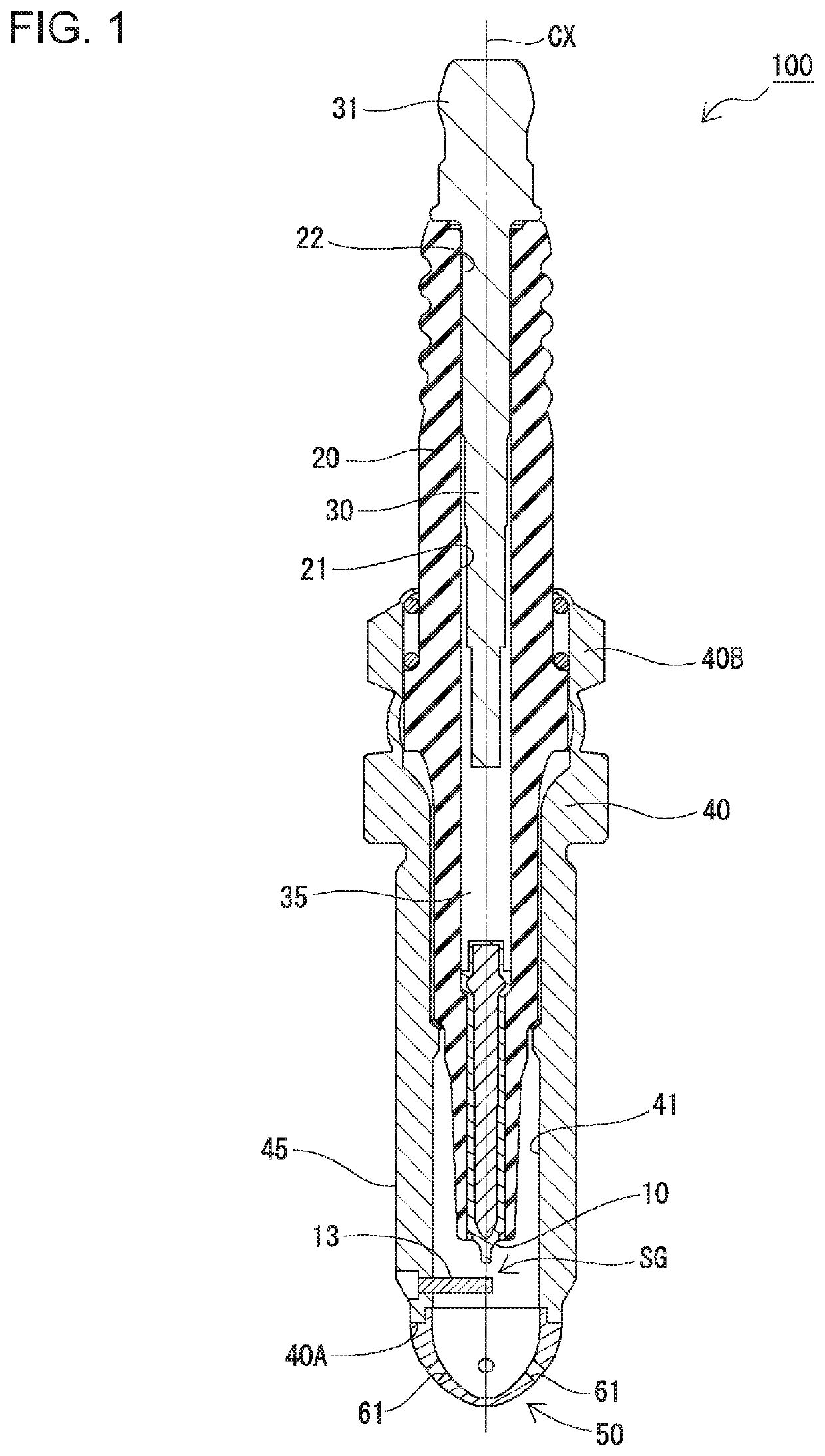
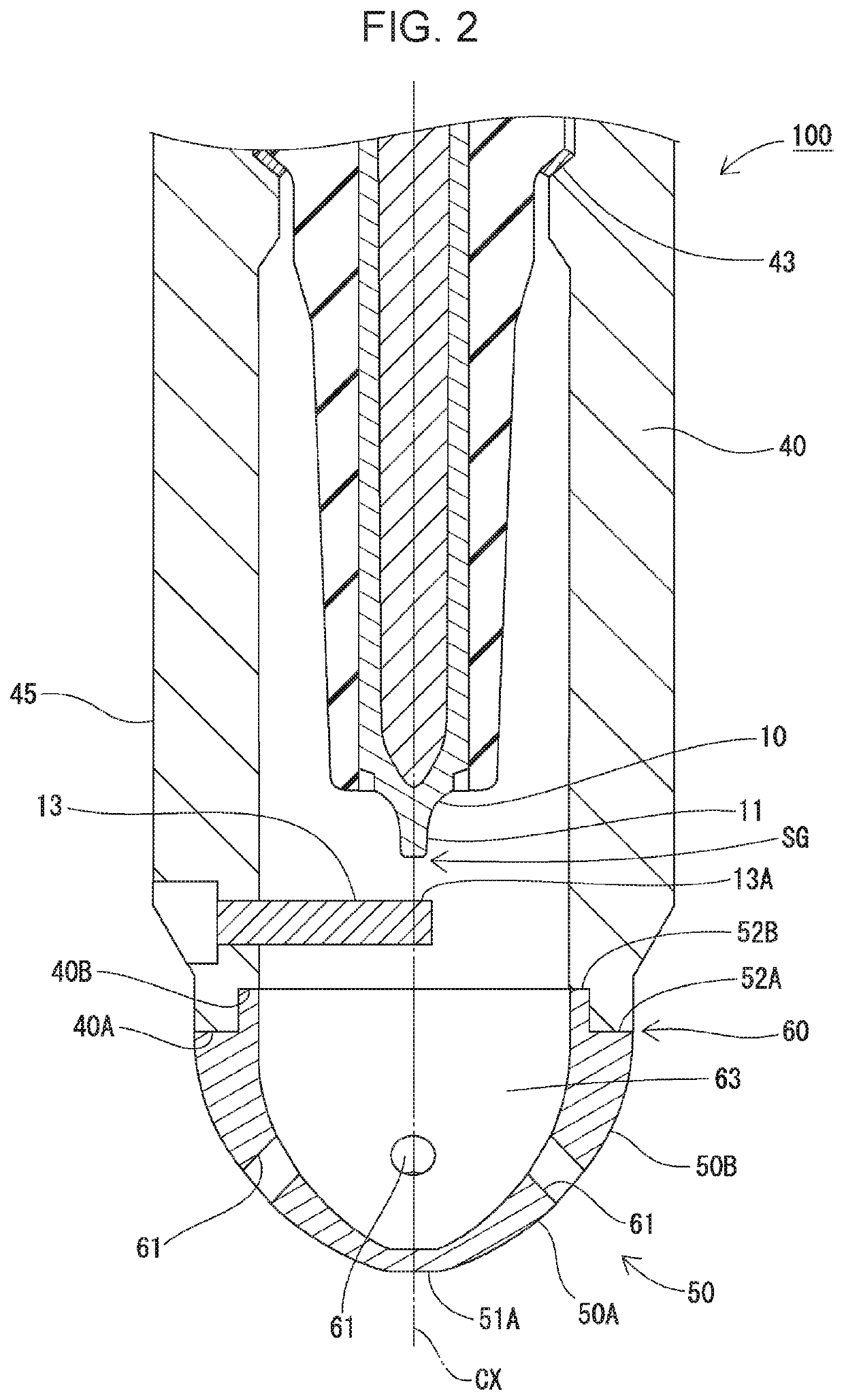
[0030]Samples of the spark plug 100 illustrated in FIGS. 1 and 2 were used herein. Table 1, below, shows the detailed conditions. The spark plug 100 satisfies the requirements of the first embodiment. In Table 1, each experiment example is denoted with “No.”. Nos. 3 to 6, 9, 10, and 12 to 18 in Table 1 are examples.
Login to View More PUM
 Abstract
A spark plug wherein the occurrence of cracks at a joint portion between a cover portion and a metal shell in the spark plug is prevented. The spark plug includes a cylindrical metal shell that accommodates an insulator therein, and a cover portion that covers, from a front end side of the spark plug, a front end portion of a center electrode and a facing portion of a ground electrode to form a pre-chamber space. The cover portion is joined to a front end side of the metal shell and has injection holes that are through-holes. A first coefficient of thermal expansion A (10−5 / K) of the material forming the cover portion at normal temperature and a second coefficient of thermal expansion B (10−5 / K) of the metal shell at normal temperature satisfy a formula (1): A<B.
Description
FIELD OF THE INVENTION[0001]The present invention relates to a spark plug.BACKGROUND OF THE INVENTIONDescription of the Related Art[0002]Spark plugs including an ignition chamber have been developed. For example, a pre-chamber ignition plug according to Japanese Unexamined Patent Application Publication No. 2012-199236 (“PTL 1”) includes a cylindrical metal housing, and an ignition chamber cap that surrounds a center electrode and a ground electrode to form an ignition chamber. The ignition chamber cap has multiple orifices that allow an air-fuel mixture to flow into the ignition chamber from a combustion chamber. This ignition plug ignites in the ignition chamber, and injects torch-shaped flames into the combustion chamber through the orifices to burn an air-fuel mixture in the combustion chamber.[0003]The ignition plug disclosed in PTL 1, however, has a structure where the ignition chamber is closed except for the orifices. Thus, the temperature inside the ignition chamber tends t...
Claims
Login to View More Application Information
Patent Timeline
 IPC IPC(8): H01T13/06H01T13/20H01T13/08
CPCH01T13/06H01T13/08H01T13/20H01T13/54H01T13/22H01T13/36H01T13/32
InventorGOZAWA, TATSUYA
OwnerNGK SPARK PLUG CO LTD