Lower vehicle-body structure of electric vehicle

Active Publication Date: 2020-11-19
MAZDA MOTOR CORP
View PDF0 Cites 9 Cited by
  • Summary
  • Abstract
  • Description
  • Claims
  • Application Information

AI Technical Summary

Benefits of technology

[0026]Thus, the lower vehicle-body structure of the electric vehicle can eliminate the need to separately provide, on the kick-up reinforcing portion, a mounting portion for mounting the long member. Also, the lower vehicle-body structure of the electric vehicle can increase rigidity of the kick-up portion a

Problems solved by technology

However, the conventional tunnel is connected to a rear part of the front floor panel and also functions as a support that supports a kick-up po

Method used


Image

  • Lower vehicle-body structure of electric vehicle
  • Lower vehicle-body structure of electric vehicle
  • Lower vehicle-body structure of electric vehicle

Examples


Example

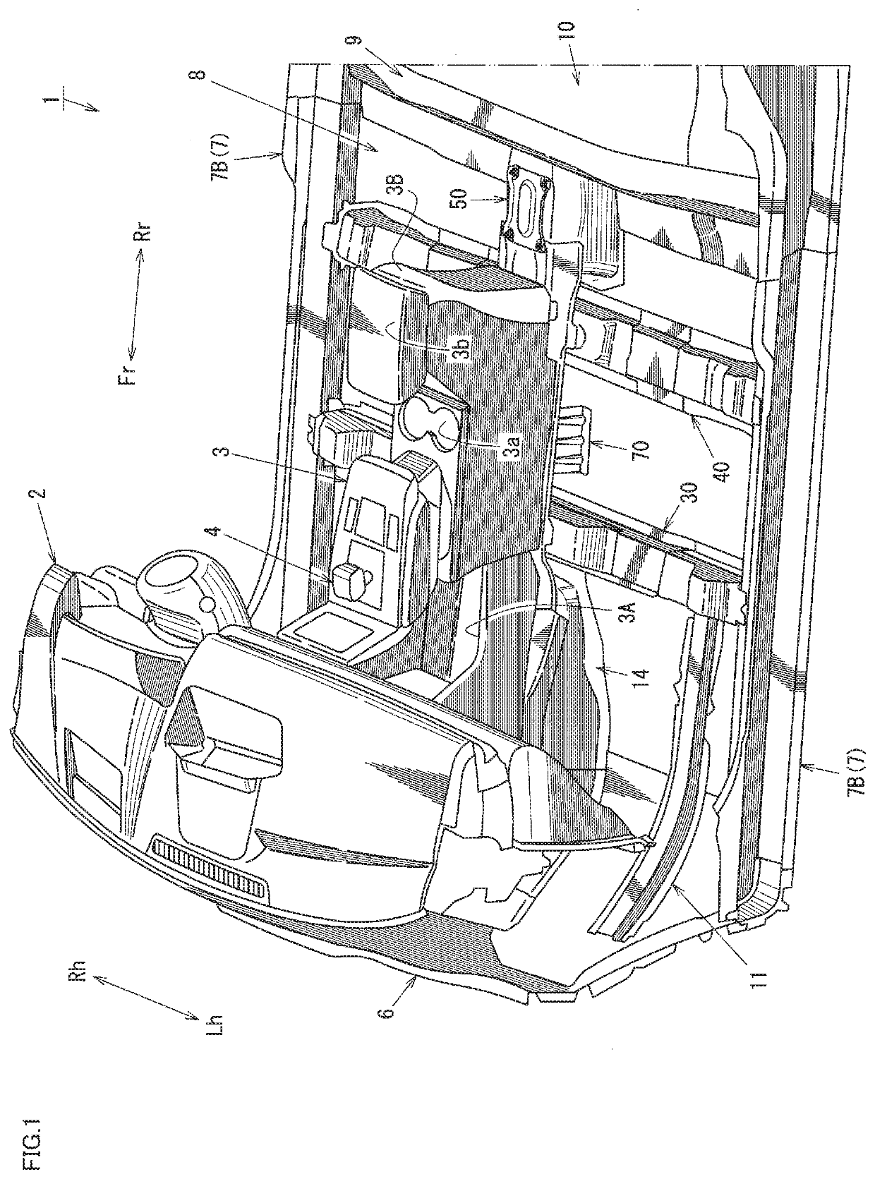
[0041]Now, with reference to the drawings, an embodiment of the present disclosure will be described. A vehicle in this embodiment is, for example, an electric vehicle that includes a battery unit such as a lithium ion secondary battery, and a rotary electric machine rotated by power supplied from the battery unit, and uses output from the rotary electric machine as a drive force. With reference to FIGS. 1 to 13, a lower vehicle-body structure in a vehicle interior part of such an electric vehicle 1 will be described in detail.

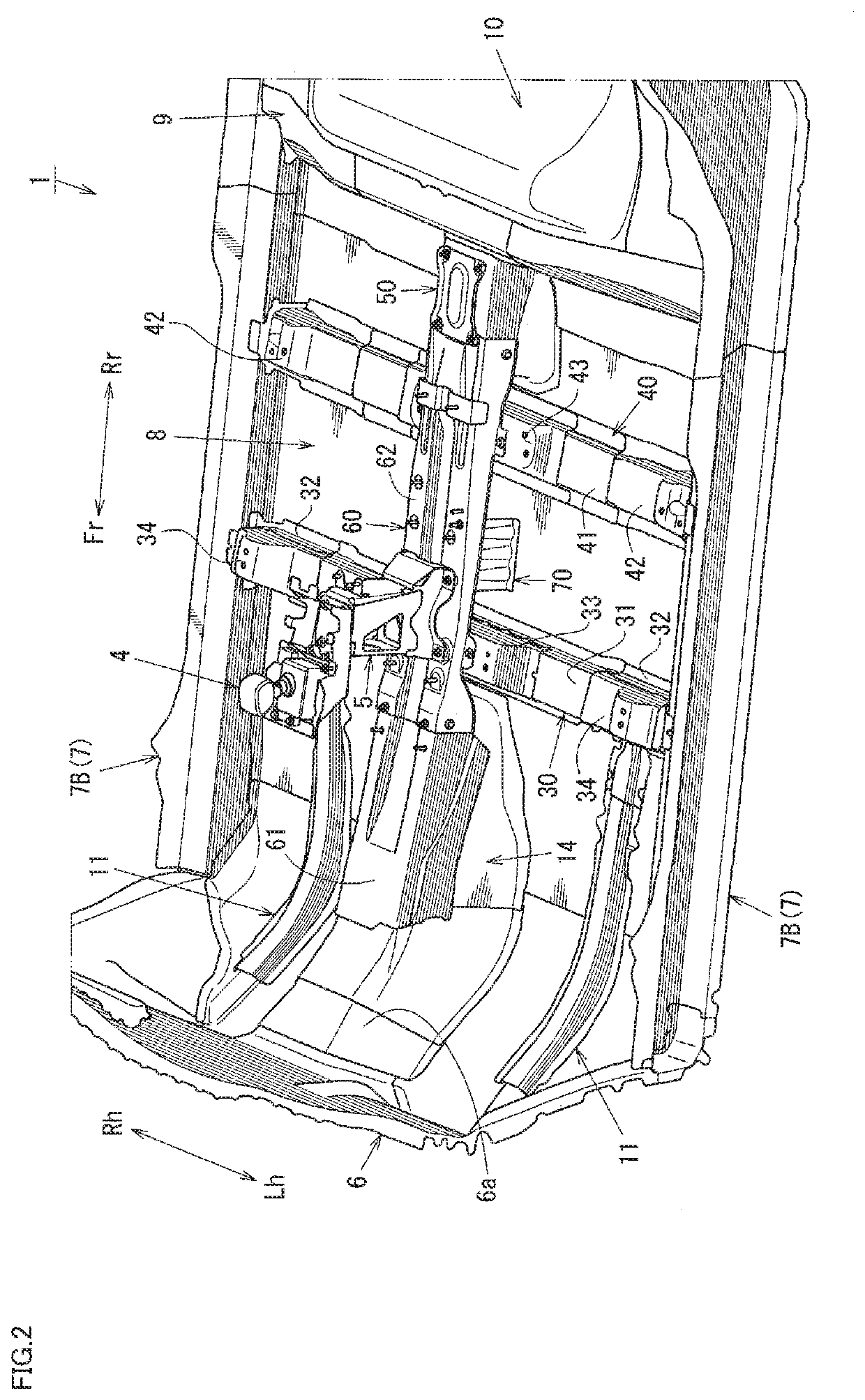
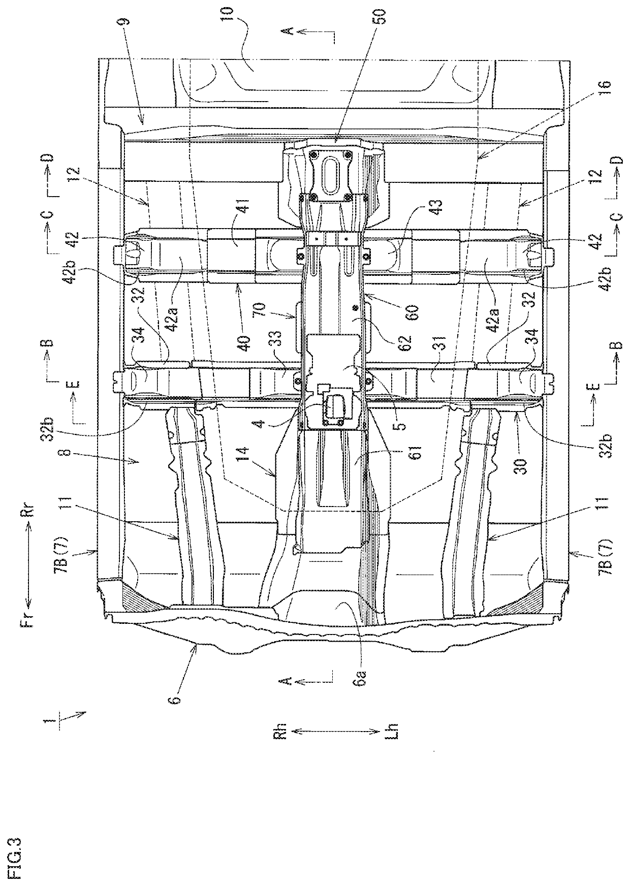
[0042]FIG. 1 is a perspective view of an appearance of a vehicle interior part of the electric vehicle 1, FIG. 2 is a perspective view of an appearance of a lower vehicle body of the electric vehicle 1, FIG. 3 is a plan view of the lower vehicle body, FIG. 4 is a sectional view taken in the direction of arrow A-A in FIG. 3, FIG. 5 is a perspective view of an appearance of an expanding member 14 viewed from a vehicle rear side, FIG. 6 is a sectional view taken ...


PUM


Abstract

A lower vehicle-body structure of an electric vehicle that can ensure desired resistance to rear-end collision even if a tunnel of a front floor panel is eliminated. The lower vehicle-body structure of the electric vehicle includes a pair of left and right side sills; a substantially flat front floor panel; a first floor cross member and a second floor cross member connecting the left and right side sills in a vehicle-width direction. The lower vehicle-body structure further includes a kick-up portion raised from a rear end of the front floor panel toward a vehicle upper side; a rear floor panel connected to a vehicle rear side of the kick-up portion; and a kick-up reinforcing element connecting a substantial middle of the kick-up portion in the vehicle-width direction and the front floor panel in front of the substantial middle of the kick-up portion.

Description

BACKGROUNDTechnical Field[0001]The present disclosure relates to a lower vehicle-body structure of an electric vehicle, for example, including no exhaust pipe on a vehicle lower side of a front floor panel.Background Art[0002]Recently, there has been a growth in the use of electric vehicles that use output from a rotary electric machine as a drive force, instead of an internal combustion engine using gasoline or the like as fuel. In such an electric vehicle, an on-vehicle battery that supplies power to the rotary electric machine is disposed, for example, on a vehicle lower side of a front floor panel that forms a vehicle interior floor surface, as described, for example, in International Publication No. WO2012 / 063393 and Japanese Patent Laid-Open No. 2013-147137.[0003]International Publication No. WO2012 / 063393 discloses a vehicle-body structure in which a floor cross member disposed on an upper surface of a front floor panel and connecting left and right side sills in a vehicle-wi...

Claims


Application Information

Patent Timeline
IPC IPC(8): B62D25/20B62D21/15B60K1/04
CPCB62D21/155B60K2001/0427B60K1/04B62D25/2036B62D27/023B62D25/20B60K2001/0438B62D25/2045B60K20/04
Inventor MATSUDA, YAMATONAKAYAMA, NOBUYUKIYAMADA, MORIHIDE
Owner MAZDA MOTOR CORP
Why Eureka
Try Eureka