System and method for purging a fuel manifold of a gas turbine engine using an accumulator
- Summary
- Abstract
- Description
- Claims
- Application Information
AI Technical Summary
Benefits of technology
Problems solved by technology
Method used
Image
Examples
Embodiment Construction
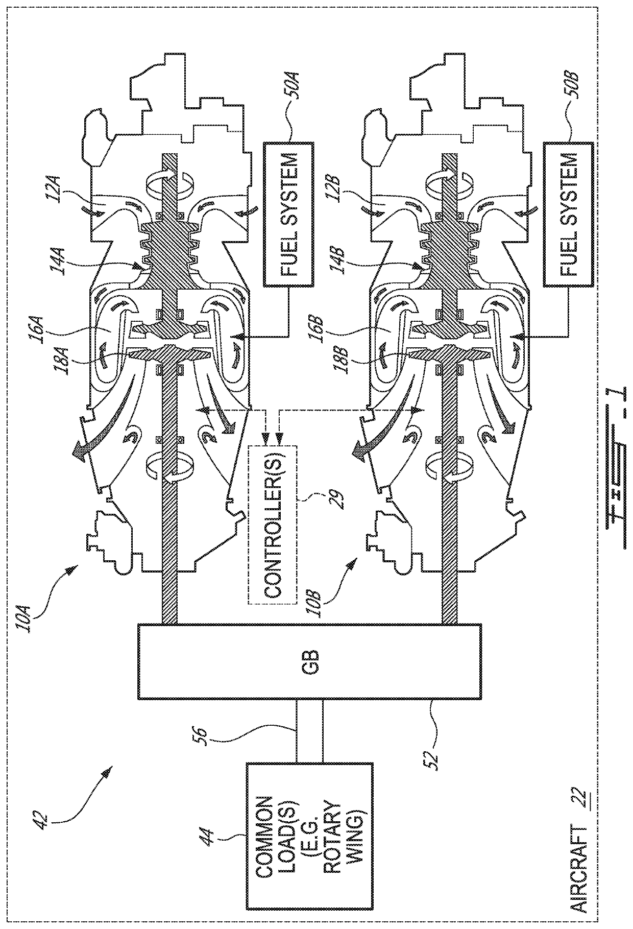
[0046]FIG. 1 schematically illustrates an exemplary multi-engine (e.g., twin-pack) power plant 42 that may be used for an aircraft 22, which may be a rotorcraft such as a helicopter. The multi-engine power plant 42 may include two or more GTEs 10A, 10B. The first gas turbine engine 10A is referred hereinafter as “FGTE 10A” and the second gas turbine engine 10B is referred hereinafter as “SGTE 10B”. In some instances FTGE 10A and / or SGTE 10B may be referred to generically as GTE 10 or GTEs 10A, 10B. In the case of a helicopter application, these GTEs 10A, 10B may be turboshaft engines. However, it is understood that methods, systems and components disclosed herein are applicable to other types of aircraft engines such as turbofans and turboprops for example.
[0047]FIG. 1 shows axial cross-section views of two exemplary GTEs 10A, 10B of the turboshaft type. Each of the GTEs 10A, 10B may comprise, in serial flow communication, respectively, air intake 12A, 12B through which ambient air ...
PUM
 Abstract
Description
Claims
Application Information
 - R&D
- Intellectual Property
- Life Sciences
- Materials
- Tech Scout
- Unparalleled Data Quality
- Higher Quality Content
- 60% Fewer Hallucinations
Browse by: Latest US Patents, China's latest patents, Technical Efficacy Thesaurus, Application Domain, Technology Topic, Popular Technical Reports.
© 2025 PatSnap. All rights reserved.Legal|Privacy policy|Modern Slavery Act Transparency Statement|Sitemap|About US| Contact US: help@patsnap.com


