Mounting and dismounting nut structure

a nut and mounting technology, applied in the direction of threaded fasteners, screws, fastening means, etc., can solve the problems of time-consuming and laborious screwing, limited operation space, and small space under the countertop, and achieve the effect of simplifying the internal structure of the mounting and dismounting nut structur

Active Publication Date: 2020-11-19
XIAMEN LOTA INT CO LTD
View PDF2 Cites 5 Cited by
  • Summary
  • Abstract
  • Description
  • Claims
  • Application Information

AI Technical Summary

Benefits of technology

[0020]Compared with existing techniques, the technical solution provided by the present disclosure has the following advantages.
[0021]1. As the mounting and dismounting nut structure comprises a limiting member in the activity chamber, when the plurality of threaded blocks is locked with the threaded rod, the limiting member supports the plurality of threaded blocks in an axial direction of the plurality of threaded blocks. Therefore, an outward movement and a downward movement of the plurality of threaded blocks caused by a looseness of the first body, resulting in a loss of an engagement force with the threaded rod, is avoided. A locking state of the plurality of threaded blocks and the threaded rod can be ensured before the plurality of threaded blocks and the threaded rod are unlocked, so an assembly of the mounting and dismounting nut structure and the threaded rod is more reliable.
[0022]2. The limiting member is disposed under the plurality of threaded blocks. When the plurality of threaded blocks is to loosen, the limiting member directly upwardly abuts the plurality of threaded blocks and limits movement or rotation of the plurality of threaded blocks is better.
[0023]3. The limiting member is operatively connected to the second body and the first body, so the limiting member can not only support the plurality of threaded blocks but also have a drive effect, which can simplify an internal structure of the mounting and dismounting nut structure and make the internal structure of the mounting and dismounting nut structure more compact and small.
[0026]6. The outer wall of the hollow sleeve ring is operatively coupled to the inner wall of the activity chamber, so the hollow sleeve ring can move upward along the activity chamber and can also drive the first body and the plurality of threaded blocks to rotate when the hollow sleeve ring moves upward to the preset position.
[0029]9. The limiting member is fixedly disposed in the activity chamber and faces the plurality of threaded blocks, resulting in the mounting and dismounting nut structure being more compact.

Problems solved by technology

The space under the countertop is quite small, and the operation space is therefore limited.
There is a problem because screwing the nut is time consuming and laborious.
If the push cover is slightly retracted during installation, the threaded block will move outward, and a clamping force between the threaded block and a pipe joint of the kitchen faucet will be lost, resulting in the installation being unreliable or even failing.

Method used


Image

  • Mounting and dismounting nut structure
  • Mounting and dismounting nut structure
  • Mounting and dismounting nut structure

Examples


embodiment 1

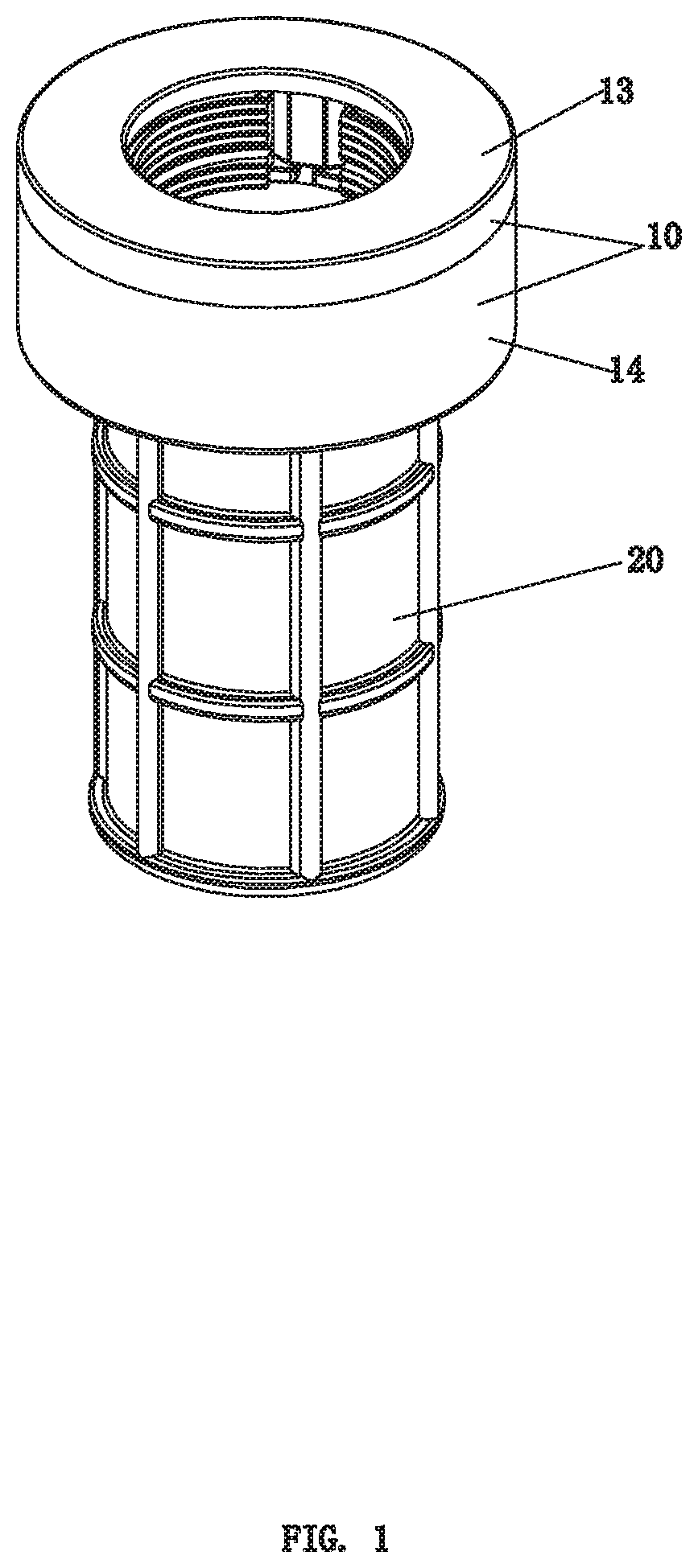
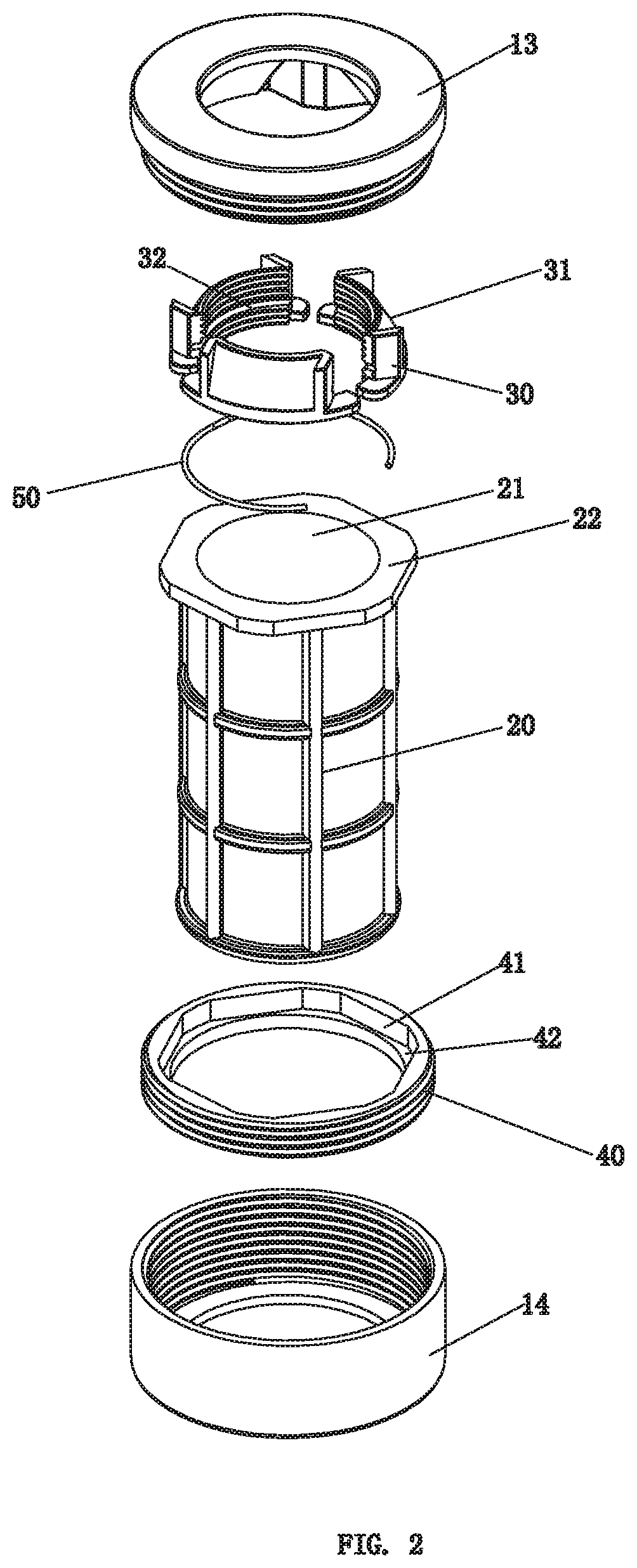
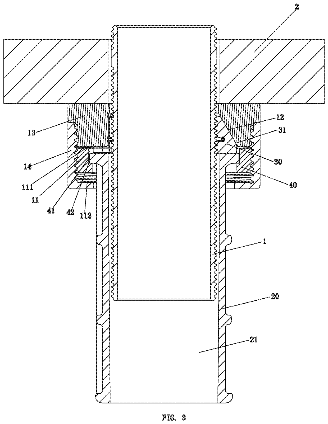
[0044]Referring to FIGS. 1-5, a mounting and dismounting nut structure of this embodiment is screwed to the threaded rod 1. The mounting and dismounting nut structure comprises a first body 10, a second body 20, a plurality of threaded blocks 30, and a limiting member 40.

[0045]The first body 10 comprises an activity chamber 11, and an inner wall of the activity chamber 11 comprises a first inclined surface 12.

[0046]In this embodiment, as shown in FIGS. 2 and 3, the first body 10 comprises a first upper body 13 and a first lower body 14 connected to the first upper body 13. The activity chamber 11 is disposed between the first upper body 13 and the first lower body 14, and the first inclined surface 12 is disposed on an inner wall surface of the first upper body 13. The first upper body 13 is fixedly screwed to the first lower body 14. Alternatively, the first upper body 13 can be connected to the first lower body 14 by welding, gluing, clamping, or screwing with loosening protective...

embodiment 2

[0065]Referring to FIG. 6, this embodiment discloses a mounting and dismounting nut structure.

[0066]This embodiment differs from Embodiment 1 in that the limiting member 40 is disposed in the activity chamber 11 and faces the three threaded blocks 30. The limiting member 40 is connected to the activity chamber 11 by integral molding, screwing, welding, clamping, sticking, etc., and is not limited thereto.

[0067]In this embodiment, the limiting member 40 comprises a limiting protrusion 43, a third limiting surface 44, and a fourth limiting surface 45 connected one-to-one (e.g., connected in series). The third limiting surface 44 is higher than the fourth limiting surface 45. The second body 20 comprises a second drive block 23 extending outward. When the second drive block 23 is connected to the fourth limiting surface 45, the second body 20 moves relative to the first body 10 in an axial direction of the second body 20. When the second body 20 rotates to enable the second drive block...


PUM


Abstract

The present disclosure disclosures a mounting and dismounting nut structure. The mounting and dismounting nut structure comprises a first body, a second body, a plurality of threaded blocks, and a limiting member. Inner walls of the plurality of threaded blocks comprise internal threads, and outer walls of the plurality of threaded blocks comprise second inclined surfaces. When the mounting and dismounting nut structure surrounds the threaded rod and is pushed towards a countertop, the plurality of threaded blocks move toward a center axis of the plurality of threaded blocks, and the second body rotates to drive the plurality of threaded blocks to be locked with the threaded rod. When the plurality of threaded blocks is locked with the threaded rod, the limiting member supports the plurality of threaded blocks in an axial direction of the plurality of threaded blocks.

Description

RELATED APPLICATIONS[0001]This application claims priority to Chinese Patent Application 201910402413.5, filed on May 15, 2019. Chinese Patent Application 201910402413.5, is incorporated herein by reference.FIELD OF THE DISCLOSURE[0002]The present disclosure relates to a mounting and dismounting nut structure.BACKGROUND OF THE DISCLOSURE[0003]At present, the kitchen faucet is mainly installed near the wall and is limited by the shape of a sink. The space for locking the kitchen faucet under the countertop is very small, and most of the kitchen faucets are fixed to sinks by a threaded connection. According to a current locking operation using a nut and a screw, the nut must be rotated from a lower end of the screw. The different thicknesses of the counters determine the effective length of the screw, which determines the length that the nut must be screwed. The space under the countertop is quite small, and the operation space is therefore limited. There is a problem because screwing...

Claims


Application Information

Patent Timeline
Patent Type & Authority Applications(United States)
IPC IPC(8): F16B39/12F16B39/18F16B37/08
CPCF16B39/122F16B39/126F16B37/0864F16B39/18F16B37/145
Inventor YU, DEZHENGWU, YUZHENGMA, QINGSHUIZHAN, HUOSHENGZHU, CHUANBAO
Owner XIAMEN LOTA INT CO LTD
Why Eureka
Try Eureka