Valve device

Active Publication Date: 2020-11-19
MIKUNI CORP
View PDF0 Cites 2 Cited by
  • Summary
  • Abstract
  • Description
  • Claims
  • Application Information

AI Technical Summary

Benefits of technology

The valve device described in this patent prevents the influence of heat from high-temperature fluids, and allows for precise opening and closing of passages.

Problems solved by technology

In addition, if laser welding or the like is used to suppress deformation caused by welding heat, equipment cost will increase, dimension management of the welded portion will be strict, and manufacturing cost will increase.
However, the valve device does not have any structure or the like for attaching the drive unit.

Method used


Image

  • Valve device
  • Valve device
  • Valve device

Examples


Embodiment Construction

[0030]An embodiment of the present invention is described below with reference to the accompanying drawings.

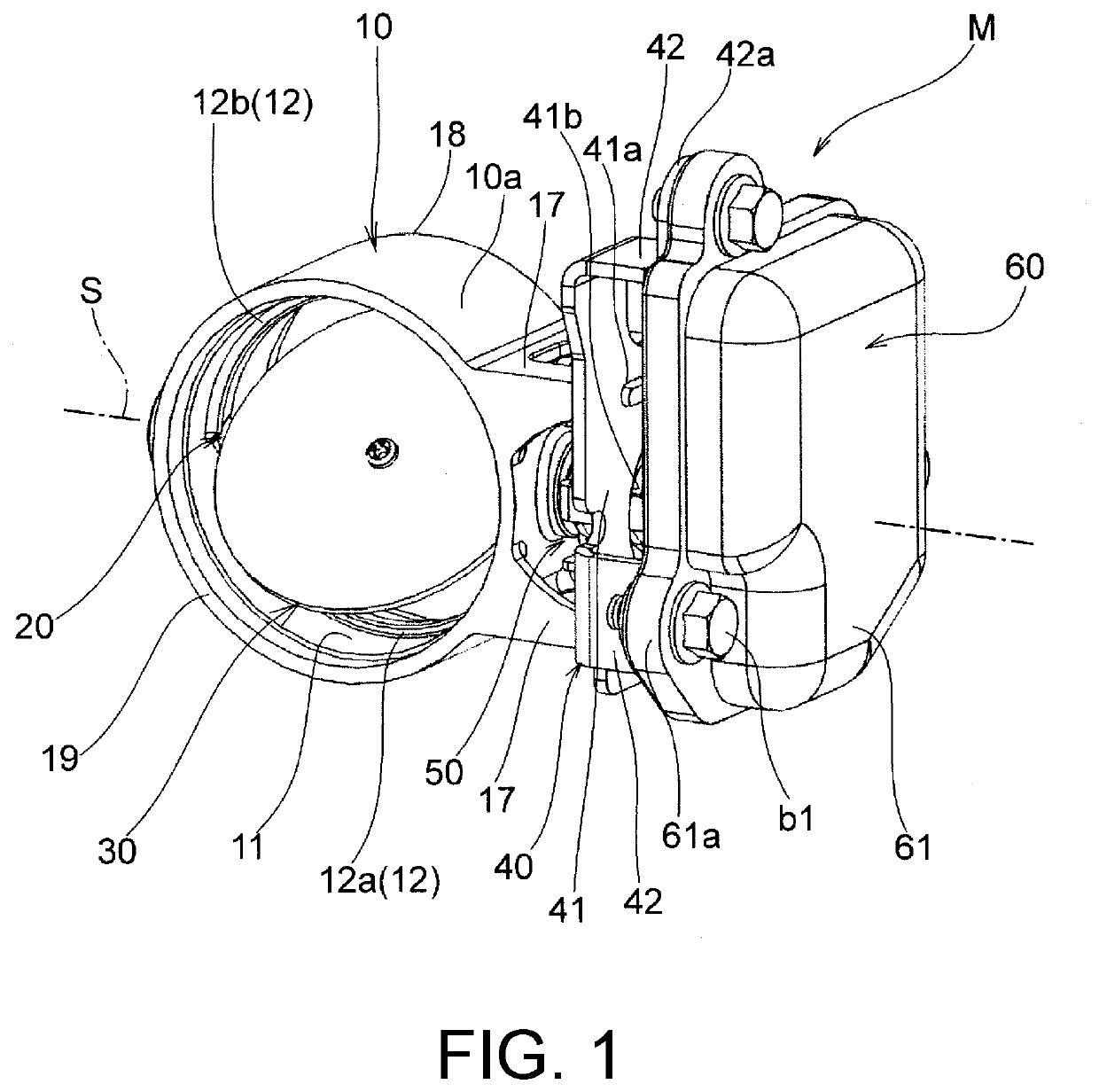
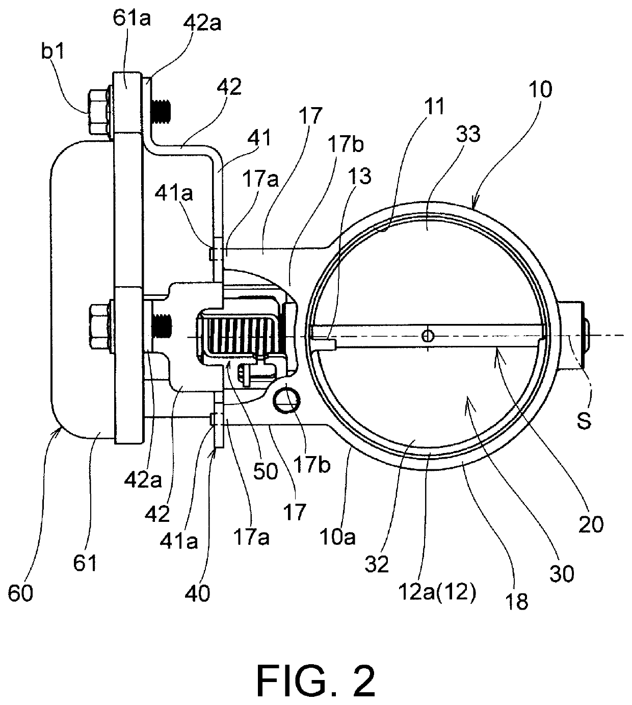
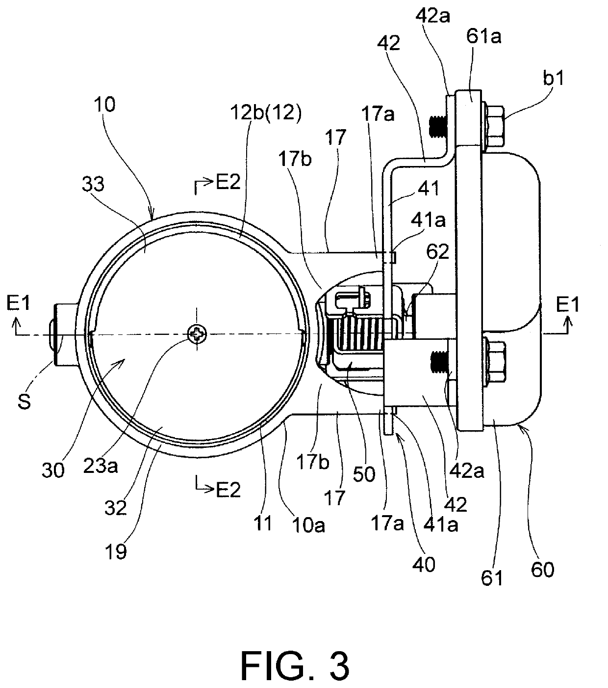
As shown in FIGS. 1 to 5, a valve device M according to the embodiment includes a body 10, a valve shaft 20 having an axis S, a butterfly valve 30, a bracket 40, a connection mechanism 50, and a drive unit 60.

[0031]The body 10 is a cast product cast with a lost wax method using a metal material such as stainless steel, iron or the like.

The body 10 includes a passage 11 through which fluid passes, a seal portion 12 formed protruding in the passage 11, a full-open stopper 13 formed protruding in the passage 11, two valve shaft holes 14 through which the valve shaft 20 passes, two fitting holes 15 for fitting bushes B, a concave portion 16 for fitting a cap C, a plurality of legs 17 serving as a protrusion portion for fixing the bracket 40, a first connection portion 18, and a second connection portion 19.

[0032]The passage 11 is formed as a cylindrical passage having a circular c...


PUM


Abstract

A valve device of the present invention includes: a body (10) defining a passage (11) through which fluid flows; a valve shaft (20) pivotably supported by the body; a butterfly valve (30) fixed to the valve shaft to open and close the passage; and a drive unit (60) configured to impart a rotational drive force to the valve shaft. The body has a protrusion portion (17) formed integrally in a manner of protruding from an outer wall (10a) of the body, and the drive unit (60) is fixed to the body (10) via the protrusion portion (17). Accordingly, influence of heat of high-temperature fluid can be suppressed or prevented, and the opening and closing operation can be performed with high precision.

Description

BACKGROUND OF THE INVENTIONTechnical Field[0001]The present invention relates to a valve device including a butterfly valve for opening and closing a passage through which high-temperature fluid flows, for example, a valve device, such as an exhaust system of an engine or the like, applied when opening and closing a passage through which high-temperature exhaust gas.Related Art[0002]A conventional valve device may include a pipe member being cylindrical and defining a fluid passage, a valve shaft inserted crossing the pipe member, a support portion arranged in the pipe member for supporting both end portions of the valve shaft, a butterfly valve being disc-shaped and fixed to the valve shaft to open and close the fluid passage, and an abutting portion which is welded to an inner wall of the pipe member for the butterfly valve to abut against when the abutting portion is closed, and the like (for example, see patent literature 1).[0003]In the valve device, the abutting portion agains...

Claims


Application Information

Patent Timeline
IPC IPC(8): F16K1/22F16K27/02F16K31/04
CPCF16K1/221F16K27/029F16K31/047F01N13/08F16K27/0218F16K31/043F02D9/04F02D9/1065F02D2009/0264
Inventor TANAKA, NAOKISUZUKI, KEIGOTAKAYAMA, DAISUKETOBE, KATSUNARI
Owner MIKUNI CORP
Why Eureka
Try Eureka