Systems and methods for controlling a power amplifier output

Active Publication Date: 2020-11-19
EMPOWER RF SYST
View PDF0 Cites 0 Cited by
  • Summary
  • Abstract
  • Description
  • Claims
  • Application Information

AI Technical Summary

Benefits of technology

The patent text describes a system for controlling the output of a power amplifier. The technical effect of the patent is to provide techniques for controlling the output of a power amplifier that improve upon traditional techniques. Specifically, the patent describes a method for controlling the output of a power amplifier that can blank or mute the output signal at various times, and a compensation mechanism to maintain the output power as the stimulus frequency changes. The patent also describes the use of frequency hopping to control the output of the power amplifier. Overall, the patent aims to provide more effective and efficient control of power amplifier output.

Problems solved by technology

It can also be desirable to mute the power amplifier (e.g., temporarily disable the power amplifier) at certain times. However, controlling the output of a power amplifier can be challenging.

Method used


Image

  • Systems and methods for controlling a power amplifier output
  • Systems and methods for controlling a power amplifier output
  • Systems and methods for controlling a power amplifier output

Examples


Embodiment Construction

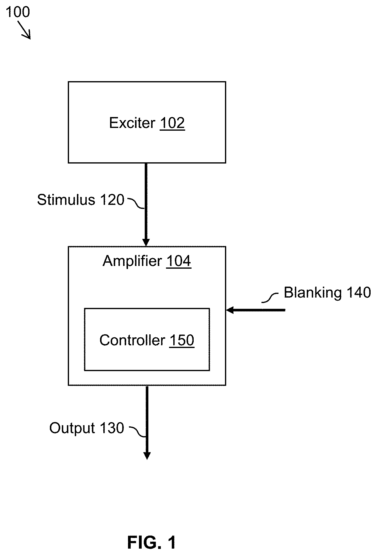
[0009]FIG. 1 is a simplified diagram of a system 100 for generating an amplified signal according to some embodiments. System 100 includes an exciter 102 coupled to an amplifier 104. Exciter 102 generates, and amplifier 104 receives, a stimulus signal 120. Based on stimulus signal 120, amplifier 104 generates an output signal 130, which generally corresponds to an amplified version of stimulus signal 120. In general, stimulus signal 120 and output signal 130 may correspond to broadband and / or radio frequency (RF) signals.

[0010]In various applications, such as communications or electronic warfare systems, it is desirable to blank (or mute) output signal 130 at various times. For example, it may be desirable to blank output signal 130 at a duty cycle in a range of 10% to 90% to provide opportunities for system 100 to listen to other signals (e.g., other RF signals) in the environment. Accordingly, amplifier 104 may receive a blanking signal 140 that indicates when output signal 130 sh...


PUM


Abstract

Techniques for controlling the output of a power amplifier are disclosed. In one embodiment, the techniques may be realized as a system that includes a power amplifier and a controller coupled to the power amplifier to form a feedback loop. The power amplifier is enabled or disabled in response to a blanking signal. The controller includes an accumulator that stores an accumulated error of the feedback loop. The controller suspends operation of the accumulator when (1) a level of the input signal is below a first threshold for an amount of time that exceeds a second threshold, (2) the blanking signal indicates that the power amplifier is disabled, or (3) both. The controller resumes operation of the accumulator when (1) the level of the input signal is above the first threshold and (2) the blanking signal indicates that the power amplifier is enabled.

Description

RELATED APPLICATIONS[0001]This application claims priority under 35 U.S.C. § 119(e) to U.S. Provisional Patent Application No. 62 / 847,725, entitled “Systems and methods for controlling a power amplifier output,” filed May 14, 2019, which is incorporated by reference herein in its entirety.FIELD OF THE DISCLOSURE[0002]The present disclosure generally relates to power amplifiers and, more particularly, to techniques for controlling the output of a power amplifier.BACKGROUND OF THE DISCLOSURE[0003]Power amplifiers may be used in a wide variety of applications, from communications to electronic warfare systems. Often, it is desirable to keep the output of the power amplifier (e.g., the output power level, the gain, etc.) constant or nearly constant during operations. It can also be desirable to mute the power amplifier (e.g., temporarily disable the power amplifier) at certain times. However, controlling the output of a power amplifier can be challenging. For example, many power amplifi...

Claims


Application Information

Patent Timeline
IPC IPC(8): H03F3/20H03G3/30
CPCH03F2200/451H03F3/20H03G3/3042H03G2201/103H03G2201/307H03F2200/129H03F3/245H03F3/19H03F2200/207H03F2200/195H03F2200/411H03F2200/211H03F1/3247
Inventor WIKE, DONALD M.STEVENSON, STEVECORREA, PAULO
Owner EMPOWER RF SYST
Why Eureka
Try Eureka