Lidar device

Pending Publication Date: 2020-12-10
ROBERT BOSCH GMBH
View PDF5 Cites 1 Cited by
  • Summary
  • Abstract
  • Description
  • Claims
  • Application Information

AI Technical Summary

Benefits of technology

The present invention relates to a LIDAR device for use in motor vehicles. The technical effects of this invention include minimizing the design of the device, making it easier to install in different locations and reducing the effort needed for providing an exit aperture. Additionally, the invention allows for different angle resolutions in different space areas and enhances eye safety by emitting measuring beams in multiple directions. Furthermore, the invention provides a safety shutdown for the LIDAR device in case of close objects.

Problems solved by technology

As a result, the height of the exit aperture may not be designed to be arbitrarily small in this way, but it also considerably depends on the technical implementation of the reception architecture of the LIDAR device.

Method used


Image

  • Lidar device
  • Lidar device
  • Lidar device

Examples


Embodiment Construction

[0029]One feature of the present invention is in particular to provide an example, improved LIDAR device, in particular in terms of a geometry aspect.

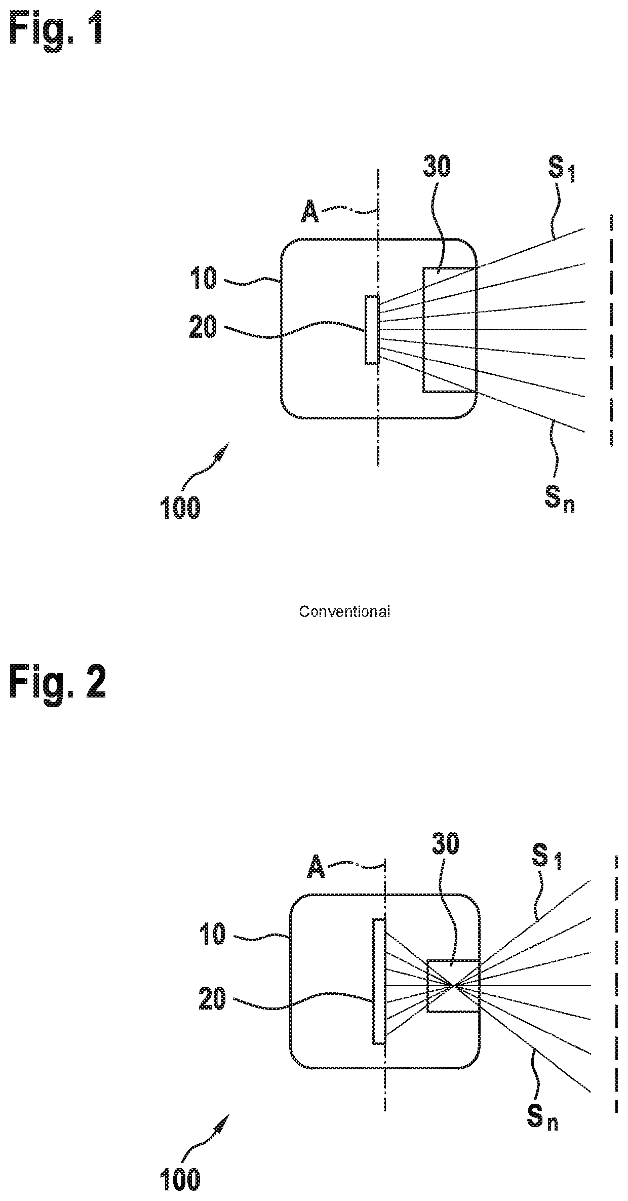
[0030]FIG. 1 shows a cross sectional view of a conventional LIDAR device 100. A housing 10 is apparent, in which an emitter device 20, which emits measuring beams S1. . . Sn through an exit aperture 30 or an exit window outwardly into the surroundings, is situated rotatably about a rotation axis A. In this way, a rotatable or rotating LIDAR device 100 (also referred to as spinning LIDAR) is designed whose transceiver device is rotatably situated about rotation axis A. These types of rotating LIDAR sensors in general have a divergent distribution of the measuring radiation, thus requiring a relatively large exit aperture 30. For exit aperture 30, a synthetic plastic, for example in the form of polycarbonate (PC) or polymethyl methacrylate (PMMA, “acrylic glass,”“plexiglass”), is usually used as the optical element, since this material i...


PUM


Abstract

A LIDAR device, including a housing, and an emitter device that is situated rotatably about a rotation axis and that is designed in such a way that the measuring beams of the emitter device intersect in the area of an exit aperture of the LIDAR device.

Description

CROSS REFERENCE[0001]The present application claims the benefit under 35 U.S.C. § 119 of German Patent Application No. DE 102019208269.6 filed on Jun. 6, 2019, which is expressly incorporated herein by reference in its entirety.FIELD[0002]The present invention relates to a LIDAR device. The present invention further relates to a method for manufacturing a LIDAR device.BACKGROUND INFORMATION[0003]LIDAR sensors will become established in the next few years when highly automated driving functions on highways and in urban surroundings are implemented. One essential property of these sensors is that the expected performance may only be achieved if the optical exit window to the surroundings is essentially free of contaminants and / or obstructions.[0004]Optoelectronic 3D scanners are available in various variants. These are to be understood as rotating macroscanners, MEMS-based scanners, OPA (optical phase array) LIDAR, Flash LIDAR. All of the aforementioned systems have in common that the...

Claims


Application Information

Patent Timeline
IPC IPC(8): G01S7/481
CPCG01S7/4814G01S7/4817G01S7/481G01S17/894G01S17/42G01S7/4813G01S17/04G01S7/497G01S7/4815G01S7/484G01S17/931
Inventor GILBERGS, HOLGER MARISRICHTER, JOHANNESGOEDEL, KARL CHRISTOPHBELL, SIMON
Owner ROBERT BOSCH GMBH
Why Eureka
Try Eureka