Eye-safe interface for optical connector

Inactive Publication Date: 2017-06-08
SAMTEC
View PDF4 Cites 7 Cited by
  • Summary
  • Abstract
  • Description
  • Claims
  • Application Information

AI Technical Summary

Benefits of technology

[0011]To overcome the problems described above, preferred embodiments of the present invention provide an optical interface with a non-symmetrical lens system so that the light exiting the optical interface is not collimated, which improves eye safety and so that beam sizes at the optical inte

Problems solved by technology

Even small dust particles can greatly increase the insertion loss and cause unwanted Fabry-Perot reflection.
The tight tolerances and the required polishing increase the cost of such fiber-to-fiber connectors.
In data com optical links, the MTP connector can be one of the most expensive components.
However, new connectors, such as PRIZM-MT by USConec, use collimated beams of light, which can cause serious eye safety issues as such a beam remains at a high intensity over long distances.
The main drawbacks of collimated-beam connectors are eye-safety issues caused by the collimated beams.
However, the collimated beam can be a serious eye-safety problem when the connector is not connected to another connector, and the collimated beam is transmitted into free

Method used


Image

  • Eye-safe interface for optical connector
  • Eye-safe interface for optical connector
  • Eye-safe interface for optical connector

Examples


Embodiment Construction

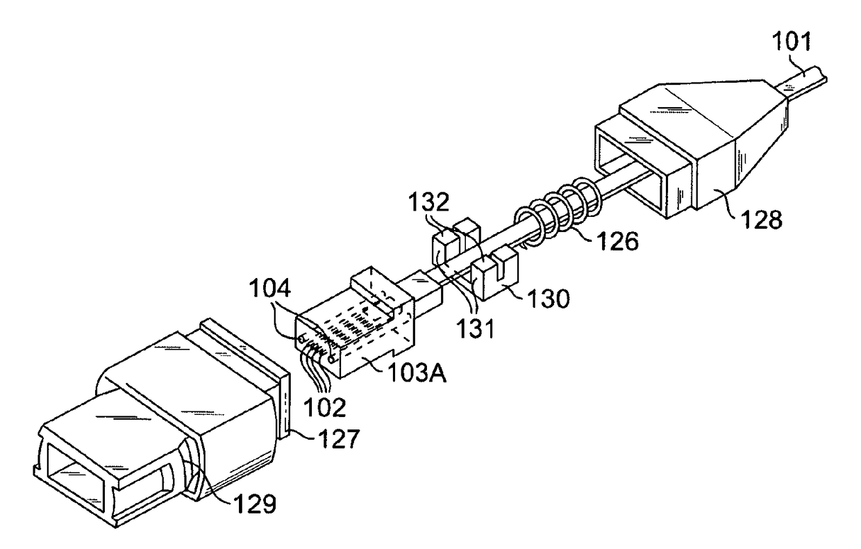
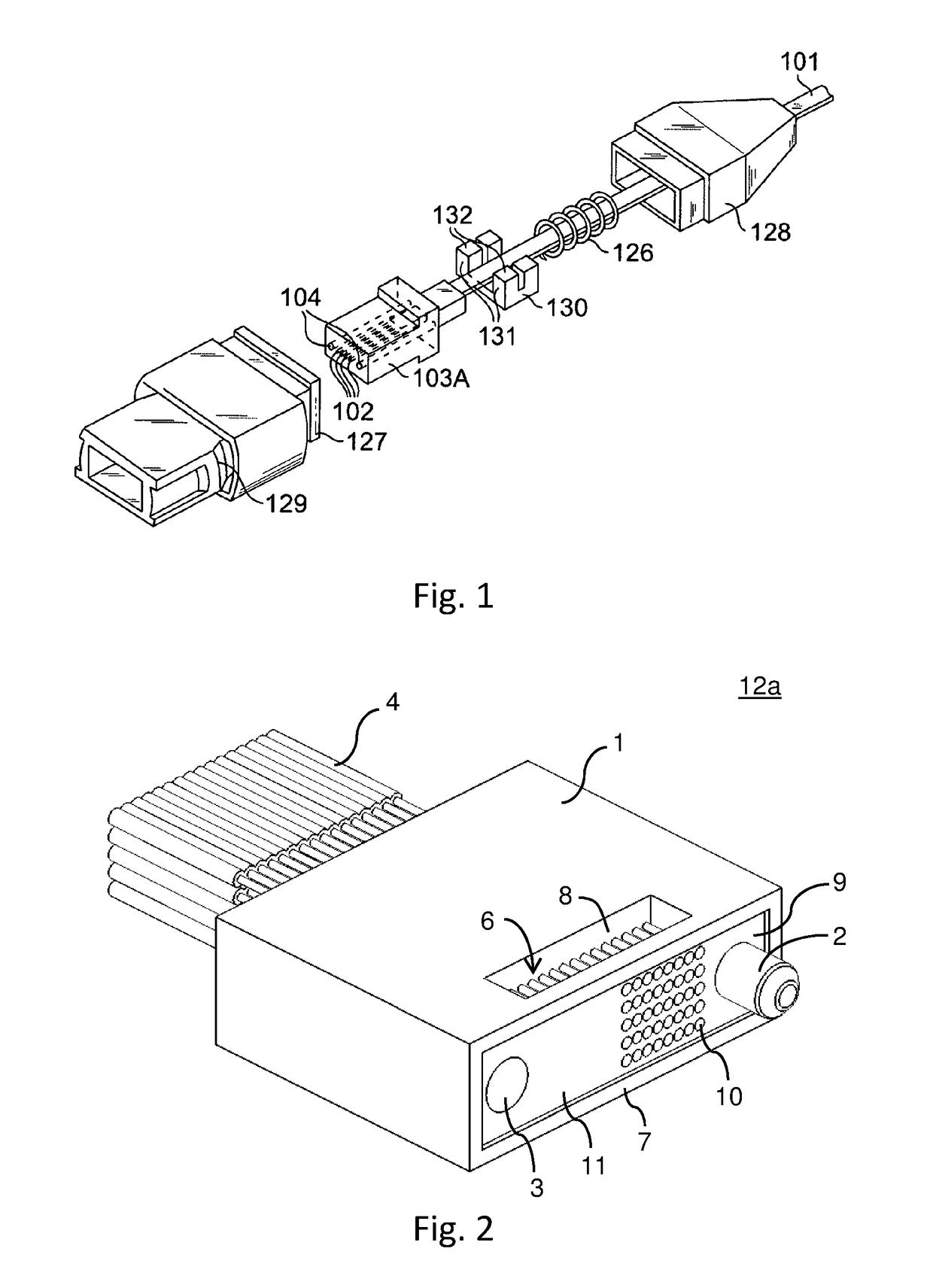
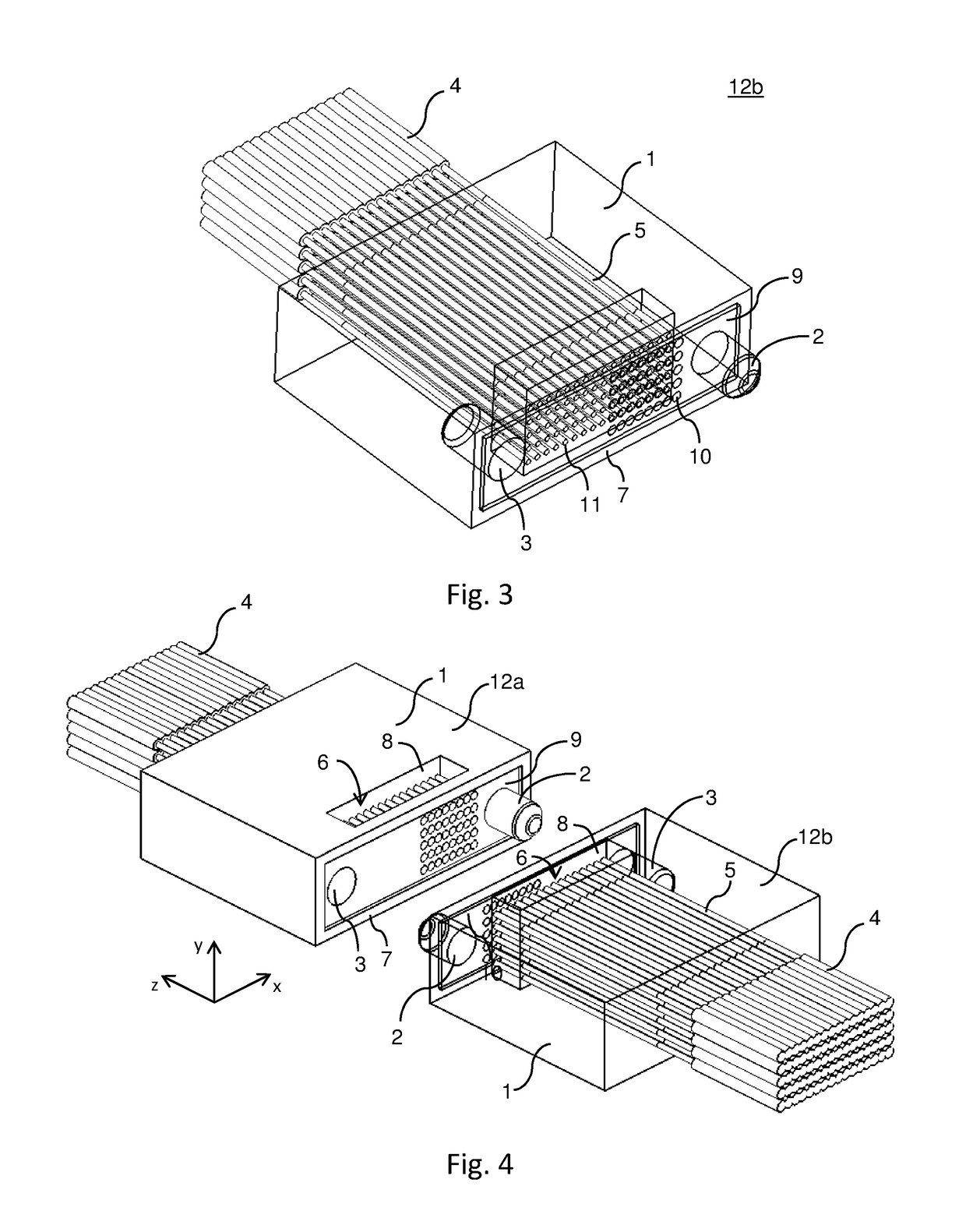
[0048]Preferred embodiments of the present are directed to an optical interface. This optical interface can be implemented as a ferrule. FIG. 1 in this application is the same as FIG. 1 of U.S. Pat. No. 7,156,561. FIG. 1 shows an example of an optical connector in which a ferrule according to preferred embodiments of the present invention can be used. The MT-type connector in FIG. 1 includes a ferrule 103A that provides a housing for the fibers 102 projecting out of the end of the ribbon 101 and that includes a pair of guide-pin insertion holes 104. The ferrules 12a, 12b shown in FIGS. 2-7 can be used as ferrule 103A in FIG. 1. A guide-pin holding member 130 behind the ferrule 103A holds the guide pins inserted into the guide-pin insertion holes 104 to prevent the guide pins from extending behind the ferrule 103A. The guide-pin holding member 130 has guide-pin holding holes 131 having inner diameters slightly smaller than those of the guide pins and having slits 132 that split the u...


PUM


Abstract

An optical connection includes a first lens with a first strength, a second lens with a second strength weaker than the first strength, a gap between the first lens and the second lenses, and optical fibers that are connected to the first and second lenses and that provide or receive light from the first and second lenses. No intermediate image is formed, and a beam of light in the gap region is either diverging or converging.

Description

BACKGROUND OF THE INVENTION[0001]1. Field of the Invention[0002]The present invention relates to optical connectors. More specifically, the present invention relates to an eye-safe interface for optical connectors.[0003]2. Description of the Related Art[0004]Some optical connectors, such as MPO and MTP connectors, use fiber-to-fiber contact to transmit light from one fiber to another. Fiber-to-fiber contact requires that the end surface of each connector be carefully polished and kept clean. Even small dust particles can greatly increase the insertion loss and cause unwanted Fabry-Perot reflection. The tight tolerances and the required polishing increase the cost of such fiber-to-fiber connectors.[0005]In data com optical links, the MTP connector can be one of the most expensive components.[0006]The light exiting an MPO or MTP connector diverges per the numerical aperture (NA) of the optical fiber. The diverging light typically does not cause an eye safety issue because the optical ...

Claims


Application Information

Patent Timeline
IPC IPC(8): G02B6/38
CPCG02B6/3853G02B6/3882G02B6/3851G02B6/383G02B6/3821G02B6/3885G02B6/325
Inventor ZBINDEN, ERIC J.
Owner SAMTEC
Why Eureka
Try Eureka