Laser eye-safety method and apparatus

a safety method and laser technology, applied in the field of explosive detection, can solve the problems of limited use of this method, optical emission, detection and analysis of these emissions may require very expensive equipment, etc., and achieve the effect of improving eye safety and limiting the range to targ

Inactive Publication Date: 2016-03-08
ENERGY RES CORP
View PDF5 Cites 19 Cited by
  • Summary
  • Abstract
  • Description
  • Claims
  • Application Information

AI Technical Summary

Benefits of technology

[0041]Additional embodiments of the invention that provide improved eye-safety include (a) limiting the range to target over which the primary laser will fire and / or (b) disposing a visible laser beam so as to be substantially coincident with said primary laser beam.

Problems solved by technology

The utility of this method generally is limited to detecting explosives characterized by high concentrations of both nitrogen and oxygen, but also having a low concentration of carbon.
Typically, such methods involve optical emissions.
Detection and analysis of these emissions may require very expensive equipment (e.g., a spectrometer).
Moreover, such optical emissions may not be unique to explosives or may be difficult to discern from emissions caused by (a) the particular substrate on which an explosive film is deposited or (b) other compounds also deposited on the substrate (e.g., dirt, grease).
Such methods also may require the use of multiple lasers, adding to the cost and complexity of the respective systems.
Significantly, the efficacy of the above methods may be limited to detection of nitrogen-based explosives, so that other types of explosives are not identified.
Finally, many of these methods are not sufficiently rapid, requiring many seconds or minutes to complete an analysis.
Thus, when such prior art methods are used to test luggage or other personal items for explosives, unacceptable delays may arise, especially under circumstances where the respective owners of the luggage or other personal items are required to wait during the test.

Method used


Image

  • Laser eye-safety method and apparatus
  • Laser eye-safety method and apparatus
  • Laser eye-safety method and apparatus

Examples


experimental examples

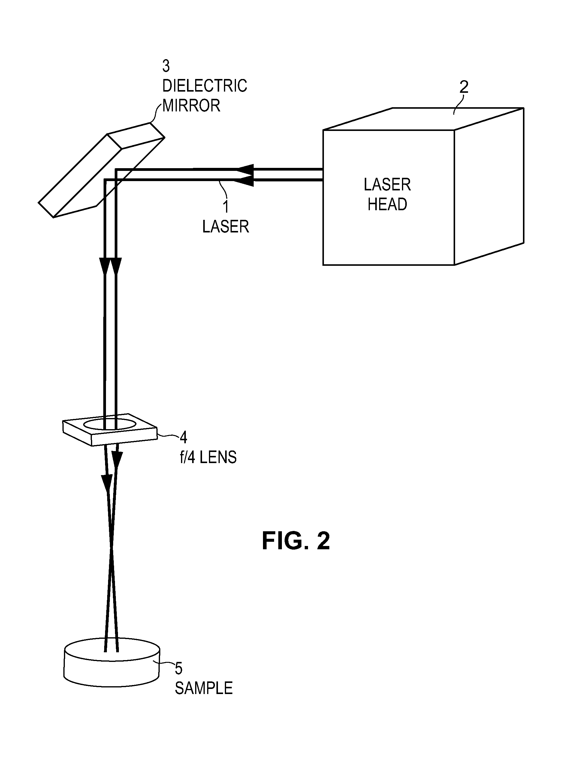
[0075]The experimental setup for the LIA measurements described in the Examples below is as shown in FIG. 2 and FIG. 3. As can be seen in FIG. 2, pulses of ultraviolet light 1 from Laser Head 2 were reflected off a 45-degree dielectric mirror 3 and directed through an f / 4 lens 4 onto a sample / target surface 5. The lens was placed such that the laser light was diverging to a diameter of 3.5 mm as it intersected the target.

[0076]LIA signals were collected using a short condensing shotgun microphone located approximately 10 meters from the target area. The microphone was connected to an amplifier that, in turn, was connected to a 500 MHz A / D data acquisition board (Acqiris Model DP235, commercially available from Agilent Technologies, Inc., Santa Clara, Calif.). The DAQ board was triggered by the laser and used to record the audio signals. FIG. 3A shows the tripod-mounted directional microphone 6 with amplifier 7. FIG. 3B depicts a view of the target 9 from the microphone 10 located 10...

example 1

LIA Measurements of Explosives in Silica Sand

[0079]LIA measurements were collected using explosives purchased from XM, a division of Van Aken International located near Los Angeles, Calif. (http: / / www.xm-materials.com / ). The explosives consisted of either TNT (trinitrotoluene), RDX, or PETN deposited on silica particles. These coated particles typically are used for training dogs to detect explosives. TNT and RDX were present at 8% by weight in their respective samples, and PETN was present at 4% by weight. Uncoated silica particles also were used, in order to reduce the weight percentages of the explosives by dilution. Samples were prepared for analysis by spreading approximately 0.6 g of material on double-sided polyethylene tape, which was attached to the underside of a 37 mm diameter aluminum sample pan. Samples were irradiated at 266 nm from a CFR-400 laser (commercially available from Quantel USA, Bozeman, Mont.).

[0080]The LIA threshold of “explosive-free” silica on tape was d...

example 2

LIA Measurements of Non-Explosive in Silica Sand

[0083]Further comparative experiments using naphthalene demonstrated that the LIA results presented in Example 1 may indeed be unique to explosives. Naphthalene is a non-explosive substance having a core molecular structure similar to that of TNT, as seen in FIG. 7. (The core structure of each molecule contains a benzene ring.)

[0084]To test the selectivity of LIA, experiments were conducted to see if adding naphthalene to silica produced LIA results different from that of TNT added to silica. A quantity of 99% pure naphthalene was ground and then mixed with silica sand to form an 8% naphthalene mixture for direct comparison with the 8% TNT coated silica sample tested in Example 1. LIA data were collected using the procedure of Example 1 on that sample and on additional mixtures with lower naphthalene concentrations, until a threshold was reached where the LIA disturbance was no longer detectable.

[0085]Experiments on these samples demon...


PUM

PropertyMeasurementUnit
energyaaaaaaaaaa
wavelengthaaaaaaaaaa

Abstract

A method and apparatus are described for detecting the presence of explosives. The invention utilizes Laser Induced Acoustics (LIA), wherein an area of a substrate surface is irradiated, via deep UV pulsed laser, with laser pulses to generate a detectable audible signal. The invention also provides substantial improvements in the eye-safety of otherwise potentially harmful laser beams. Thus, the invention is particularly well-suited to use in public venues where detection of explosives or improved laser safety may be required.

Description

CROSS-REFERENCE TO RELATED APPLICATIONS[0001]This application claims priority to U.S. Provisional Application No. 61 / 518,118, filed Apr. 29, 2011, and is a divisional of U.S. Ser. No. 13 / 459,956, filed Apr. 30, 2012.BACKGROUND OF THE INVENTION[0002]1. Field of the Invention[0003]The invention relates to the detection of explosives in public locations and, more particularly, to a method and apparatus for detecting trace amounts of explosives on various surfaces.[0004]Increasingly, public safety and the safety of government and military personnel depends on the detection of hidden explosives in venues such as airports and other transportation terminals, subway entrances, border crossings, sporting events, concerts, and other public gatherings. The presence of an explosive film or explosive particles on a surface is a possible indicator that larger amounts of explosives are nearby. For example, an explosive-laden fingerprint on a car's trunk lid, as may be detected by the present inven...

Claims


Application Information

Patent Timeline
Patent Type & Authority Patents(United States)
IPC IPC(8): G01N33/22
CPCG01N33/227G01N33/22G01N21/1702G01N21/65G01N21/718G01N2021/1706B23K37/006
Inventor WEISBERG, AREL
Owner ENERGY RES CORP
Why Eureka
Try Eureka