Lidar sensor for optically detecting a field of view and method for optically detecting a field of view

a technology of optical detection and field of view, applied in the direction of instruments, measurement devices, using reradiation, etc., can solve the problem that the failure of a single light source to reflect only as a decrease in the overall intensity, and achieve the effect of flexible installation space configuration, small installation space, and flexible installation space configuration

Pending Publication Date: 2022-07-21
ROBERT BOSCH GMBH
View PDF0 Cites 0 Cited by
  • Summary
  • Abstract
  • Description
  • Claims
  • Application Information

AI Technical Summary

Benefits of technology

[0013]An advantage of the present invention is that the LIDAR sensor needs a smaller installation space. Due to the plate-shaped light guide optics, a more flexible installation space configuration may be enabled. Due to the at least two optical fibers, a more flexible installation space configuration may be enabled. The alignment of the emission unit and the receiving unit with respect to one another is more easily possible. It requires few adjustment steps.
[0014]In one advantageous embodiment of the present invention, it is provided that the plate-shaped light guide optics may include at least one fiber bundle. The advantage of this embodiment is that the fiber bundle is flexibly adaptable to the geometry of the light source. In this way, each fiber of the fiber bundle may include a coupling end for coupling the primary light generated by the light source and a decoupling end for decoupling guided primary light. The coupling ends may be flexibly adaptable to the geometry of the light source. In this way, the coupling ends may be, for example, linearly situated when the light source is linearly designed. However, if the light source is designed, for example, to be planar, the coupling ends of the fiber bundle may have an arrangement suitable for coupling primary light generated by this planar light source. The decoupling ends may be linearly situated in both examples.
[0015]In one advantageous embodiment of the present invention, it is provided that the at least two optical fibers are situated in a curved manner. The advantage of this embodiment is that the placement of the detector unit is freely selectable. The detector unit may be placed in various ways with respect to the light source. This has advantages with respect to the cooling of the detector unit and the electromagnetic compatibility.
[0016]In one further advantageous embodiment of the present invention, it is provided that the plate-shaped light guide optics is designed in such a way that the generated primary light is mixable. For this purpose, the plate-shaped light guide optics may be designed to be curved. The advantage of this embodiment is that a more homogeneous illumination of the field of view may be implemented. Eye safety may be improved. In addition, the failure of a single emitter of the light source is reflected only as a decrease in the overall intensity. In this case, all image points may nevertheless continue to be illuminated.
[0017]In one further advantageous embodiment of the present invention, it is provided that the generated primary light is mixable in at least two subareas of the plate-shaped light guide optics situated separately from one another. The advantage of this embodiment is that the primary light may have different optical properties in each of the various subareas. Primary light having different optical properties may be mixed in the subareas separately from one another.
[0018]In one further advantageous embodiment of the present invention, it is provided that generated primary light of at least two wavelengths, which differ from one another, is guidable to the beam exit with the aid of the plate-shaped light guide optics. Here, the generated primary light is mixable in at least two subareas of the plate-shaped light guide optics situated separately from one another. The advantage of this embodiment is that, in the field of view, for example, one row may be illuminated with the aid of different wavelengths. This is advantageous in order to simulate the angle dependence of a receiving filter. This has advantages for eye safety, a more homogeneous illumination of the field of view may be implemented, and the failure of a single emitter of the light source is reflected only as a decrease in the overall intensity. In this case, all image points may nevertheless continue to be illuminated.

Problems solved by technology

In addition, the failure of a single emitter of the light source is reflected only as a decrease in the overall intensity.

Method used


Image

  • Lidar sensor for optically detecting a field of view and method for optically detecting a field of view
  • Lidar sensor for optically detecting a field of view and method for optically detecting a field of view
  • Lidar sensor for optically detecting a field of view and method for optically detecting a field of view

Examples


Embodiment Construction

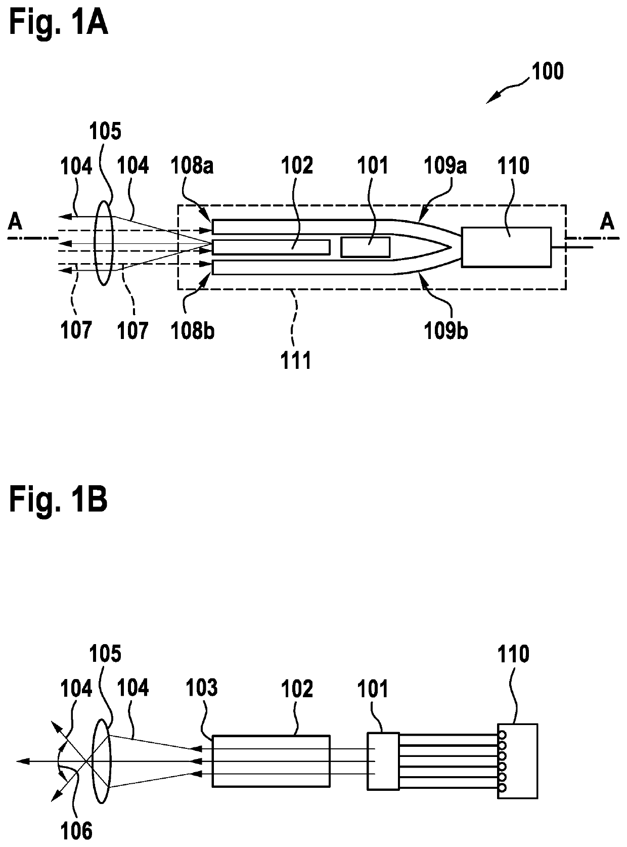
[0035]FIG. 1A shows, by way of example, a first exemplary embodiment of a LIDAR sensor 100 in the top view. The LIDAR sensor includes an emission unit for emitting primary light 104 into a field of view and a receiving unit for receiving secondary light 107, which was reflected and / or scattered in the field of view by an object. Here, the emission unit includes a light source 101 for generating primary light 104, a plate-shaped light guide optics 102 including a beam exit 103 for guiding generated primary light 104, and emission optics 105, which is designed here as an optical lens 105, for emitting guided primary light 104 into the field of view. The plate-shaped light guide optics 102 is designed for guiding primary light 104 generated by light source 101 to beam exit 103. Beam exit 103 is located in the imaging plane of emission optics 105. The receiving unit includes a receiving optics 105, which is designed here as an optical lens 105, for receiving secondary light 107. Emissio...


PUM


Abstract

A LIDAR sensor for optically detecting a field of view. The LIDAR sensor includes an emission unit for emitting primary light into the field of view and a receiving unit for receiving secondary light, which was reflected and/or scattered in the field of view by an object. The emission unit includes: a light source for generating the primary light; a plate-shaped light guide optics including a beam exit for guiding the generated primary light; and at least one emission optics for emitting the guided primary light into the field of view. The receiving unit includes: at least one receiving optics for receiving secondary light; at least two optical fibers, each including a beam entrance for guiding the received secondary light; and at least one detector unit for detecting the guided secondary light. The emission optics and the receiving optics are situated coaxially to one another.

Description

FIELD[0001]The present invention relates to a LIDAR sensor for optically detecting a field of view, in particular for a working device, a vehicle, or the like, and to a method for optically detecting a field of view.BACKGROUND INFORMATION[0002]German Patent Application No. DE 10 2016 213 348 A1 describes an optical system for a LIDAR system for optically detecting a field of view, in particular for a working device or for a vehicle, including an receiver optics designed in a segmented manner including an—in particular odd-numbered—plurality of optically imaging segments, in which the optically imaging segments of the receiver optics are situated next to one another.SUMMARY[0003]The present invention is directed to a LIDAR sensor for optically detecting a field of view. In accordance with an example embodiment of the present invention, the LIDAR sensor includes an emission unit for emitting primary light into the field of view and a receiving unit for receiving secondary light, which...

Claims


Application Information

Patent Timeline
Patent Type & Authority Applications(United States)
IPC IPC(8): G01S7/481G01S17/89G01S13/931
CPCG01S7/4812G01S7/4818G01S7/4817G01S13/931G01S7/4814G01S17/89
Inventor SCHWARZ, HANS-JOCHENSCHUMANN, ANNEBELING, HORSTSTOPPEL, KLAUSNAEGELE, MARCOKASTNER, MARTIN
Owner ROBERT BOSCH GMBH
Why Eureka
Try Eureka