
Beam characterization

a beam characterization and beam technology, applied in the field of wireless communication, can solve the problems of high propagation loss of millimeter wave channels, complicated generation of codebooks, and complex wireless communication devices, so as to improve the accuracy and utility of measurement information, improve the performance of beam forming for wireless communication devices, and improve the effect of beam forming gain

Pending Publication Date: 2020-12-10
QUALCOMM INC
View PDF6 Cites 2 Cited by
  • Summary
  • Abstract
  • Description
  • Claims
  • Application Information

AI Technical Summary

Benefits of technology

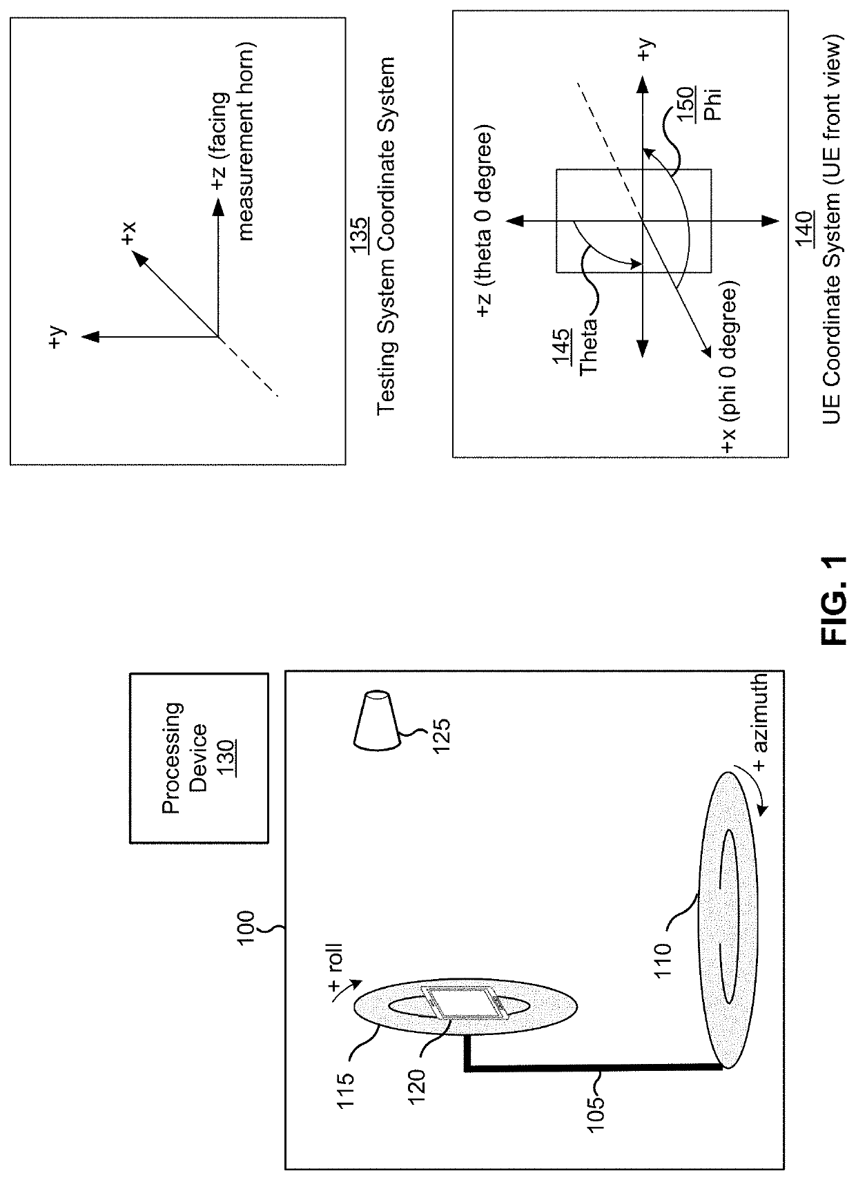
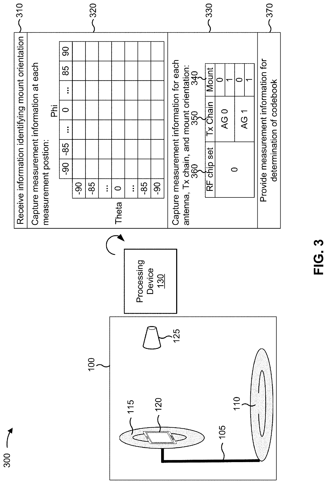
This patent provides techniques and devices for measuring the electric field of a wireless communication device based on its orientation relative to a testing chamber. The measurement can be done per antenna, rather than for an entire antenna group, which improves accuracy. Codebooks can be generated based on this measurement information or simulated electric field information to improve beamforming and reduce inaccuracy. These techniques and devices can enhance the performance of wireless communication devices by improving beamforming and reducing nonuniformity.

Problems solved by technology

Millimeter wave channels may suffer from high propagation loss.
However, the interaction of different antennas, the complexity of the wireless communication device's geometry, and other concerns may complicate the generation of the codebook.
Furthermore, the measurement of the wireless communication device's electric field, if performed while a plurality of antennas are active (as opposed to being performed while a single antenna is active), may not provide sufficient granularity of information to enable optimization of the codebook.
Still further, different testing systems may use different coordinate systems, thereby complicating determination of measurement information and increasing likelihood of error.

Method used


Image

  • Beam characterization
  • Beam characterization
  • Beam characterization

Examples


Embodiment Construction

[0033]Various aspects of the disclosure are described more fully hereinafter with reference to the accompanying drawings. This disclosure may, however, be embodied in many different forms and should not be construed as limited to any specific structure or function presented throughout this disclosure. Rather, these aspects are provided so that this disclosure will be thorough and complete, and will fully convey the scope of the disclosure to those skilled in the art. Based on the teachings herein one skilled in the art should appreciate that the scope of the disclosure is intended to cover any aspect of the disclosure disclosed herein, whether implemented independently of or combined with any other aspect of the disclosure. For example, an apparatus may be implemented or a method may be practiced using any number of the aspects set forth herein. In addition, the scope of the disclosure is intended to cover such an apparatus or method which is practiced using other structure, functio...


PUM


Abstract

Various aspects of the present disclosure generally relate to wireless communication and testing. In some aspects, a device may receive information identifying a mount orientation of a wireless communication device, wherein the mount orientation indicates an orientation of a coordinate system of the wireless communication device relative to a coordinate system of a positioner. The device may capture measurement information at each position of a set of positions of the wireless communication device, wherein the set of positions comprises positions of the wireless communication device as the wireless communication device is rotated around an axis by the positioner, and wherein the measurement information is captured based at least in part on the mount orientation. The device may provide information identifying the measurement information. Some techniques and apparatuses described herein may use the measurement information to generate a codebook for beam generation. Numerous other aspects are provided.

Description

CROSS-REFERENCE TO RELATED APPLICATION[0001]This patent application claims priority to Provisional Patent Application No. 62 / 858,975, filed on Jun. 7, 2019, and to Provisional Patent Application No. 62 / 869,874, filed on Jul. 2, 2019, both entitled “BEAM CHARACTERIZATION” (“the Priority Applications”). The disclosure of the Priority applications is considered part of and is incorporated by reference in this patent application as if fully set forth below in its entirety and for all applicable purposes.TECHNICAL FIELD[0002]Aspects of the technology described below generally relate to wireless communication and to techniques and apparatuses for beam characterization. Some techniques and apparatuses described herein enable and provide wireless communication devices and systems configured for efficient radio component usage.INTRODUCTION[0003]Wireless communication systems are widely deployed to provide various telecommunication services such as telephony, video, data, messaging, and broad...

Claims


Application Information

Patent Timeline
IPC IPC(8): H04B17/364H04B7/08
CPCH04B17/364H04B7/0814H04B7/0413H04B7/0822H04B7/0456H04B7/0619H04B7/0691H04B7/0695H04B7/0874H04B7/088
Inventor CAI, MINGMINGCHALLA, RAGHU NARAYANSUNDARA RAGHAVAN, REVATHIBURKE, MICHAELBANGALORE RAVI, ABHILASHLAGHATE, MIHIR VIJAYPATEL, SHRENIKPARK, SANG-JUNETASSOUDJI, MOHAMMAD ALIKRISHNAN, SUDARSANRAGHAVAN, VASANTHANKAMATH, SIDDHARTH
Owner QUALCOMM INC
Learn More