
Dual speed rotary tool

Active Publication Date: 2020-12-17
FIRST EASTERN EQUITIES LTD
View PDF3 Cites 0 Cited by
  • Summary
  • Abstract
  • Description
  • Claims
  • Application Information

AI Technical Summary

Benefits of technology

The patent describes a device that controls the flow of air in a turbine engine. When the device is in a certain position, it allows air to flow through certain parts of the engine, which results in a higher speed. When the device is in another position, it blocks the air flow and results in a lower speed. This technology helps to improve the performance of turbine engines.

Problems solved by technology

This results in a lower speed.

Method used


Image

  • Dual speed rotary tool
  • Dual speed rotary tool
  • Dual speed rotary tool

Examples


Embodiment Construction

[0021]As required, detailed embodiments are disclosed herein; however, it is to be understood that the disclosed embodiments are merely examples and that the systems and methods described below can be embodied in various forms. Therefore, specific structural and functional details disclosed herein are not to be interpreted as limiting, but merely as a basis for the claims and as a representative basis for teaching one skilled in the art to variously employ the disclosed subject matter in virtually any appropriately detailed structure and function. Further, the terms and phrases used herein are not intended to be limiting, but rather, to provide an understandable description.

[0022]The present invention provides a high torque dual speed rotor for hand held or machine mounted applications. The present invention leverages current designs for high speed rotors with two or more annular chambers for the turbine by using a two piece shaft with an internal flow control screw. Moving the inte...


PUM


Abstract

A high torque dual speed turbine rotor for a lightweight hand held tool for grinding and polishing or for use with a spindle mounted pneumatic machine. The high torque dual speed turbine rotor includes a two-piece shaft with flow control screw disposed within the shaft. The shaft includes a first set of hollow openings, at a first position from one end of the shaft, in fluid communications with a first annular chamber of a rotor. There is also a second set of hollow opening, at a second position from the one end of the shaft, in fluid communications with a second annular chamber of the rotor. The flow control screw moves inside a threaded axial bore of the shaft from an open position inside the axial bore to the closed position corresponding to the second set of hollow openings.

Description

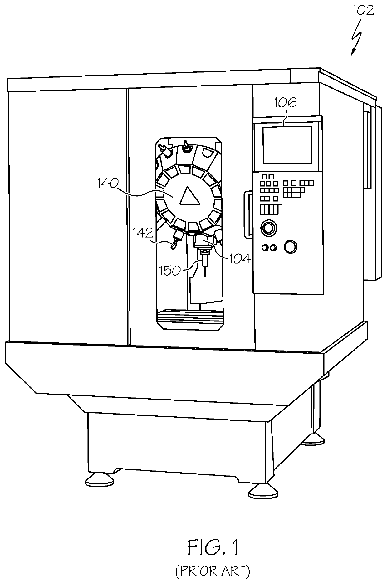
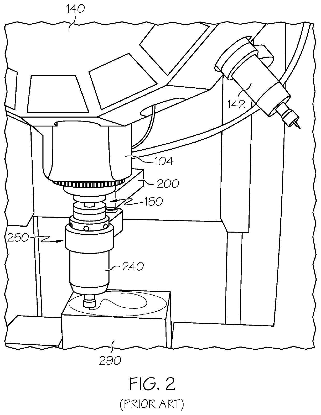
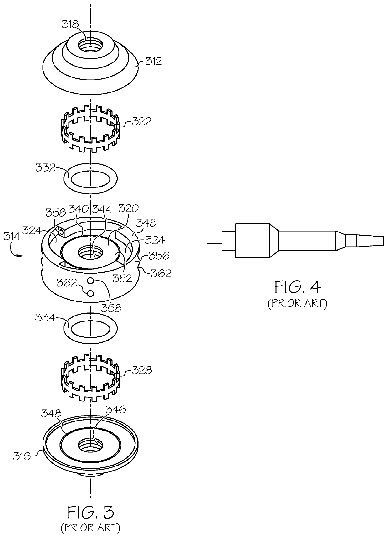
CROSS-REFERENCE TO RELATED APPLICATIONS[0001]This application claims priority from and is related to the following prior application U.S. Provisional Application No. 62 / 860,538, filed Jun. 12, 2019 entitled “DUAL SPEED ROTARY TOOL.” This prior application, including the entirety of the written description and drawing figures, is hereby incorporated into the present application by reference.FIELD OF THE INVENTION[0002]This disclosure relates generally to pneumatically powered, hand held or spindle-mounted lightweight tool suitable for grinding and polishing and, more particularly, to a turbine rotor for a lightweight, grinding tool driven by an air-powered reaction turbine.BACKGROUND[0003]In the prior art, lightweight pneumatic tools have been used for a variety of functions, such as grinding, polishing, metal or plastic finishing, engraving, drilling, and deburring. The tool variations include hand-held and machine spindle-mounted embodiments. Hand-held tools often include a narrow ...

Claims


Application Information

Patent Timeline
IPC IPC(8): F01D15/06F01D1/02B24B23/02
CPCF01D1/02B25F5/02B24B23/02F01D15/06F01D15/067B24B23/026F01D15/065B23Q5/165F01D15/062
Inventor SHANE, SIMON RICHARD
Owner FIRST EASTERN EQUITIES LTD
Features
  • Generate Ideas
  • Intellectual Property
  • Life Sciences
  • Materials
  • Tech Scout
  • Unparalleled Data Quality
  • Higher Quality Content
  • 60% Fewer Hallucinations
Learn More