Floating Valve Seat For A Rotary Control Valve For Use In Severe Service Applications

Active Publication Date: 2020-12-17
FISHER CONTROLS INT LLC
View PDF0 Cites 2 Cited by
  • Summary
  • Abstract
  • Description
  • Claims
  • Application Information

AI Technical Summary

Benefits of technology

[0005]In accordance with a first exemplary aspect, a valve seat is provided for use in a rotary valve including a valve body and a floating ball element disposed in the valve body. The valve seat includes a seat body, a sealing element, a first bearing, and a second bearing. The seat body is adapted to selectively engage a portion of the floating ball element. The sealing element is disposed in a first groove formed in the seat b

Problems solved by technology

Although this extends the lifespan of the various components, frequent maintenance is still required.
However, because contact or adhesion between surfaces, which happens when the valve seat c

Method used


Image

  • Floating Valve Seat For A Rotary Control Valve For Use In Severe Service Applications
  • Floating Valve Seat For A Rotary Control Valve For Use In Severe Service Applications
  • Floating Valve Seat For A Rotary Control Valve For Use In Severe Service Applications

Examples


Embodiment Construction

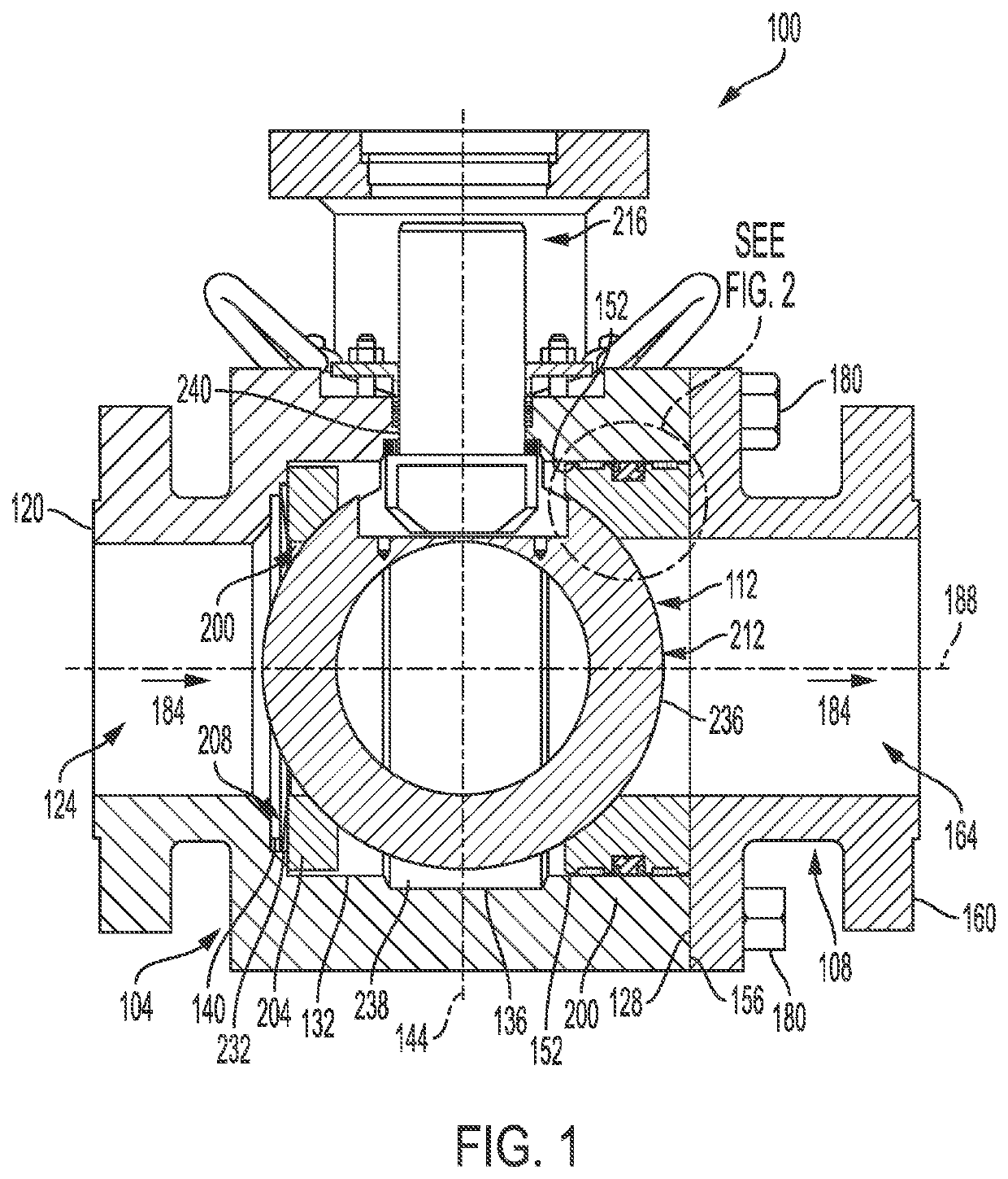
[0021]The present disclosure is directed to a valve seat for use in a rotary control valve for use in severe service applications. The valve seat is configured to move (e.g., float) within a valve body of the rotary control valve such that the valve seat sealingly engages a floating ball element of the rotary control valve when the floating ball element is in a closed position, thereby achieving the necessary shutoff. The valve seat also includes one or more sealing elements configured to effect a seal between the valve body and the valve seat. At the same time, the valve seat includes one or more bearing elements that allow the seat to move as necessary but provide the correct clearance for the one or more sealing elements and protect the seal from abrasive or corrosive material that may be present in fluid flowing in these severe service applications.

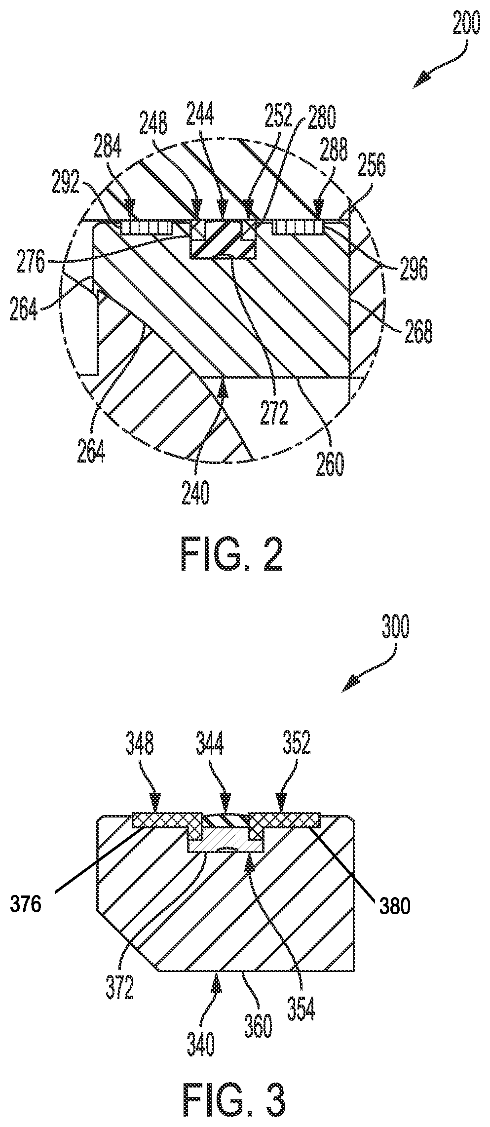
[0022]FIGS. 1 and 2 illustrate one example of a rotary control valve 100 constructed in accordance with the principles of the presen...


PUM


Abstract

A valve seat is provided for use in a rotary valve for use in highly corrosive and abrasive applications. The valve seat includes a seat body adapted to selectively engage a portion of the floating ball element. The valve seat also includes a sealing element disposed in a first groove formed in the seat body and adapted to prevent fluid flow between the seat body and the valve body. The valve seat further includes a first bearing disposed in a second groove formed in the seat body, and a second bearing disposed in a third groove formed in the seat body, wherein the second and third grooves are formed immediately adjacent the first groove such that the first and second bearings are disposed immediately adjacent the sealing element.

Description

FIELD OF THE DISCLOSURE[0001]The disclosure generally relates to rotary control valves and more specifically to a floating valve seat for a rotary control valve for use in severe service applications.BACKGROUND OF THE DISCLOSURE[0002]Process control systems often employ rotary valves, such as ball valves, butterfly valves, eccentric-disk valves, eccentric-plug valves, etc., to control the flow of process fluids. Rotary valves typically include a valve trim assembly having a seat disposed in the fluid path and surrounding a flow aperture, and a fluid control element (e.g., a disk, a ball, etc.) disposed in the fluid path and rotatably coupled to the body of the valve via a shaft. To control the flow of fluid through some rotary valves, the position of the fluid control element may be varied from a closed position at which the fluid control element is in sealing engagement with the seat, thereby preventing fluid flow through the flow aperture, to a fully open or maximum flow rate posi...

Claims


Application Information

Patent Timeline
IPC IPC(8): F16K5/20F16K5/06
CPCF16K5/201F16K5/0689F16K5/0647F16K5/08F16K5/0668F16K5/0673
Inventor LAVERTY, LARRY T.PEDERSON, KYLE D.
Owner FISHER CONTROLS INT LLC
Why Eureka
Try Eureka