System and method for determining axle load

a technology of axle load and system, applied in the field of system and method for determining axle load, can solve the problems that the axle gauge may have a tendency to separate from the vehicle, and achieve the effects of improving vehicle operation, increasing sensor reliability, and being more reliabl

Active Publication Date: 2020-12-17
DANA HEAVY VEHICLE SYSTEMS GROUP LLC
View PDF0 Cites 1 Cited by
  • Summary
  • Abstract
  • Description
  • Claims
  • Application Information

AI Technical Summary

Benefits of technology

[0005]By measuring an angle between two components of an axle system, it may be possible to estimate a load that is applied to the axle system. In particular, an axle system may include several components that form a trapezoid. In one example, the axle system may include an axle and a tie rod that form parallel sides of a trapezoid. The axle system may also include two knuckles that form the remaining sides of the trapezoid. The axle's shape may change when a heavy load is applied to the axle while the tie rod's length remains unchanged since the load that is applied to the axle is not applied to the tie rod. An angle between the axle and a knuckle may change as load is applied and removed from the axle. The angle may be indicative of the load that is applied to the axle. Therefore, an estimate of a load applied to the axle may be estimated from the angle that is between the two axle system components. Measuring the angle between the two axle system components may be more reliable than measuring axle load via a strain gauge because the axle system is free to expand and contract without the angle sensor separating from the axle system.
[0006]The present description may provide several advantages. In particular, the approach may provide axle load sensing in the presence of axle system expansion and contraction that may be due to ambient temperature. In addition, the approach may provide increased sensor reliability since the angle sensor may be exposed to a less severe environment than strain gauges. Further, the approach may communicate the estimated axle load to other vehicle systems to improve vehicle operation.

Problems solved by technology

However, strain gauges may have a tendency to separate from the vehicle when they are exposed to environmental conditions (e.g., salt, water, temperature, and dirt) and vehicle conditions (e.g., vibrations).

Method used


Image

  • System and method for determining axle load
  • System and method for determining axle load
  • System and method for determining axle load

Examples


Embodiment Construction

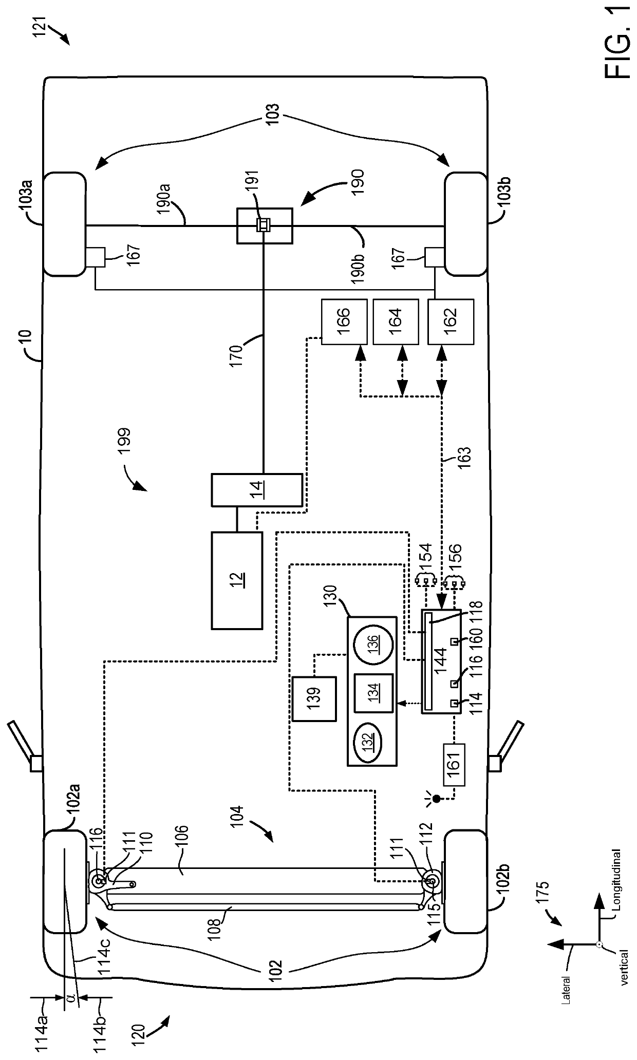
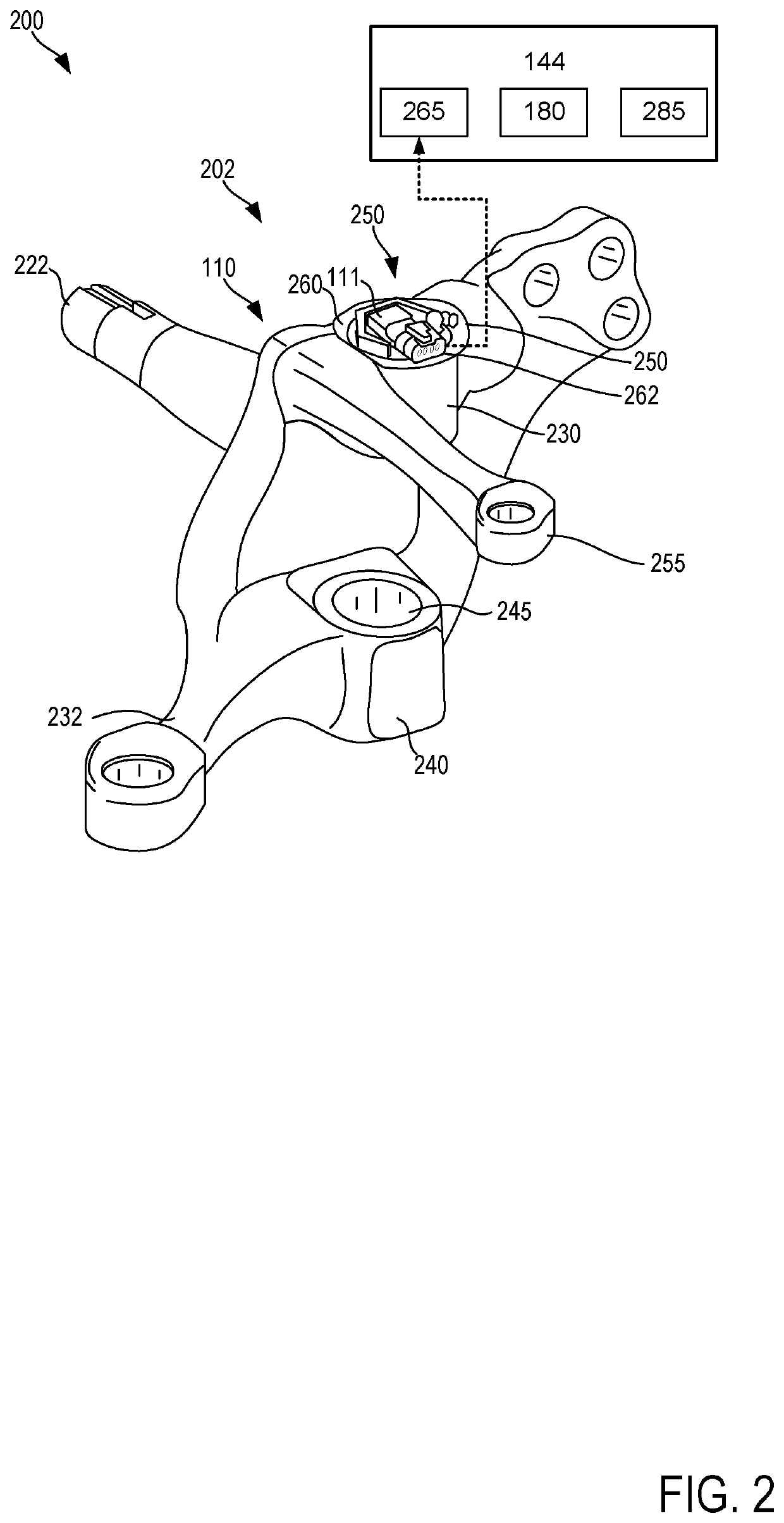
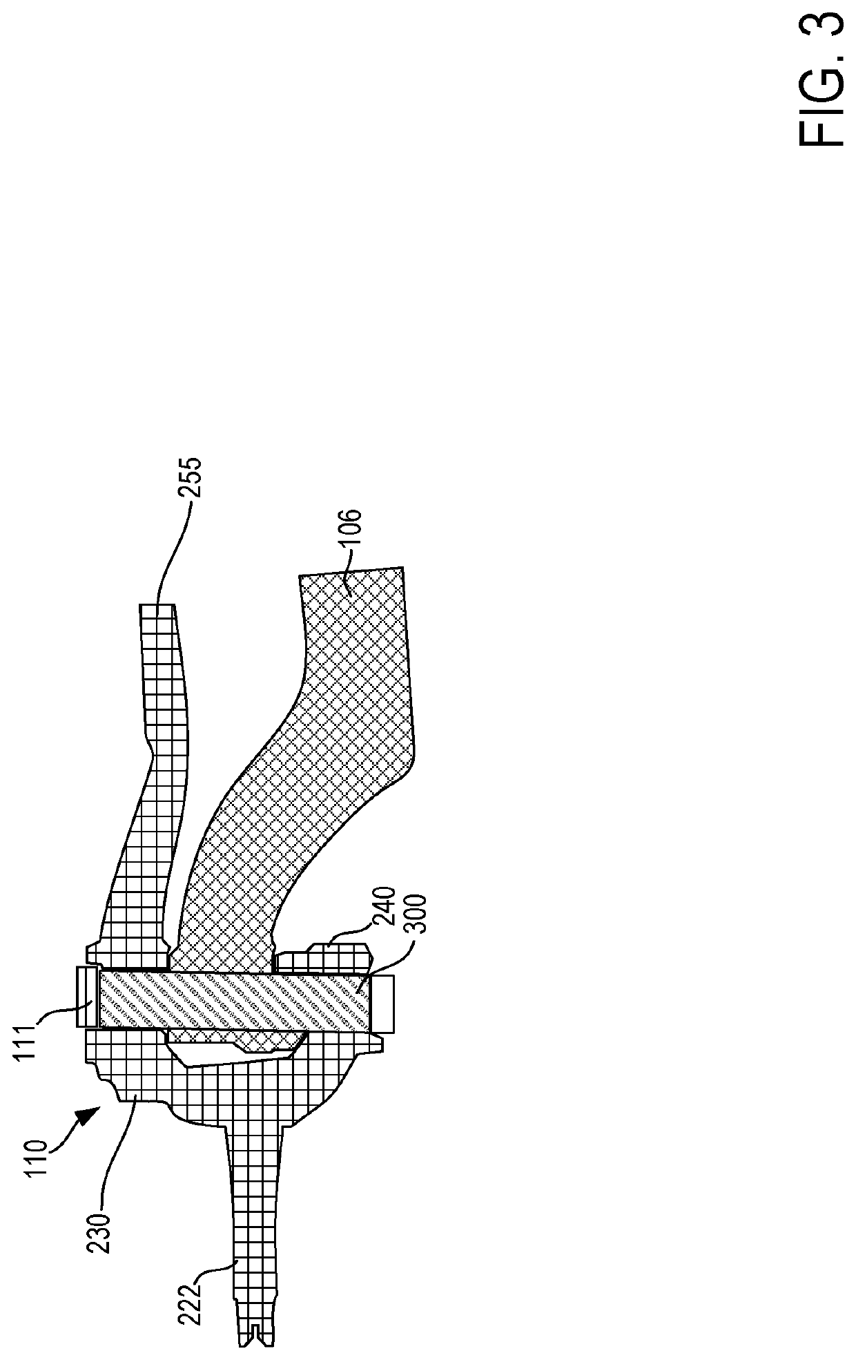
[0017]The following description relates to systems and methods for estimating axle load. The axle may be included in a vehicle that includes a propulsion source as shown in FIG. 1. The axle system may include knuckles, kingpins, a tie rod, and an axle. The knuckles may be of the type shown in FIG. 2. The kingpins may couple the knuckles to the axle as shown in FIG. 3. An angle sensor may sense an angle between two axle system components as shown in FIG. 4. FIGS. 5 and 6 show how one side of a trapezoid formed by the axle system may respond to axle load. The axle load data from the axle system may be communicated to other vehicle systems and external systems as shown in FIG. 7. A method for estimating axle load and communicating axle load is shown in FIG. 8. Finally, a relationship between an axle angle and axle load is shown in FIG. 9.

[0018]It is to be understood that the invention may assume various alternative orientations and step sequences, except where expressly specified to th...


PUM


Abstract

Methods and systems for estimating an axle load of a vehicle are described. In one example, a method is disclosed wherein axle load is estimated in response to an angle between two components of an axle. The angle may change as weight is added to or removed from the axle such that axle load may be determined as a function of the angle.

Description

CROSS-REFERENCE TO RELATED APPLICATIONS[0001]The present application claims priority to U.S. Provisional Application No. 62 / 860,982, entitled “SYSTEM AND METHOD FOR DETERMINING AXLE LOAD”, and filed on Jun. 13, 2019. The entire contents of the above-listed application are hereby incorporated by reference for all purposes.TECHNICAL FIELD[0002]The present disclosure relates to a system and method for determining the axle load of a vehicle by measuring the toe angle of each wheel of the axle.BACKGROUND AND SUMMARY[0003]The axle load of a vehicle is the total amount of weight transferred by an axle and its wheels to a road. The axle load of a vehicle may increase when weight is added to the vehicle and it may be decrease when weight is removed from the vehicle. The vehicle's total weight may influence a distance that it takes for the vehicle to come to a stop and the vehicle's stability. As such, it may be desirable to determine a vehicle's axle load. One way to determine a vehicle's ax...

Claims


Application Information

Patent Timeline
Patent Type & Authority Applications(United States)
IPC IPC(8): G01G19/08B62D7/18G01G19/18G01G19/02
CPCG01G19/18B62D7/18G01G19/086G01G19/40G01G19/028B60B35/00B62D15/023B60T8/1875B60T13/662B60T17/22B60T8/172B60T2240/06G01G19/08B60G17/0182B60G2800/70B60G2400/60B60G2200/44B60G2206/50B60G2204/11B60G2400/05144B60G2401/28B60G2401/172B60G2200/30B60G9/00B60G2300/026B60G2600/0422B60G17/0195B60W40/13B60W2556/50
Inventor DAVIS, MARK A.PASSERO, ANTHONY N.STOYCHEV, STOYAN I.
Owner DANA HEAVY VEHICLE SYSTEMS GROUP LLC
Why Eureka
Try Eureka