Shear bar

a technology of shear bars and cylinders, applied in the field of shear bars, can solve the problems of disadvantageous impairment of strength and cost, and achieve the effects of extending service life, reducing complexity of parts, and easy rotation

Active Publication Date: 2020-12-24
BETEK
View PDF0 Cites 1 Cited by
  • Summary
  • Abstract
  • Description
  • Claims
  • Application Information

AI Technical Summary

Benefits of technology

[0021]With such chopping drums, the infeed element can preferably comprise two infeed bevels that are at an angle to one another and to the cutting edge; and the infeed bevels can transition into one another directly or via a joining portion. The two rows of knife edges can run onto the same infeed element, the knife edges of the one row running onto the first infeed bevel, and the knife edges of the second row onto the second infeed bevel. Parts complexity can thereby be further decreased.
[0022]In the interest of a stable and simple design for the infeed element, provision can furthermore be made in this context that the joining portion terminates with a joining edge in the region of the cover portion, the joining edge constituting a transition between the joining portion and the cover portion. In a refinement of the invention, the joining portion can comprise a flat surface portion or a concavely curved surface portion between the two infeed bevels. With a concave curvature, the joining portion can offer a harmonious carryover into the two infeed bevels. A stress-optimized design is also thereby made possible.
[0023]If provision is made that the carrier comprises, on oppositely located sides, rows of cutting elements that each form a cutting edge; and that each of the rows of cutting elements comprises at least one infeed element, the shear bar can then be installed in such a way that one of the two cutting edges comes selectably into cutting engagement with the chopping drum. In particular, when a cutting edge is worn out, the shear bar can easily be rotated and the second cutting edge can be brought into cutting engagement. This results in an extension of service life and a decrease in parts complexity, since only one carrier needs to be utilized for two cutting edges.
[0024]In order to allow that region of the carrier which adjoins the cutting elements also to be effectively protected from wear, provision can be made that the row of cutting elements is adjoined in the region of the upper side of the carrier by a row of armor elements that are preferably constituted by plate-shaped elements made of hard material, in particular metal carbide.

Problems solved by technology

In particular, not only is this step cost-intensive, but heat energy would be introduced into the previously manufactured shear bar via the infeed element by means of the grinding process, and into the join between the infeed element and the support member of the shear bar.
The structure of the joining material (solder join, adhesive join, etc.) is thereby changed, with the result that strength can be disadvantageously impaired.

Method used


Image

  • Shear bar
  • Shear bar
  • Shear bar

Examples


Embodiment Construction

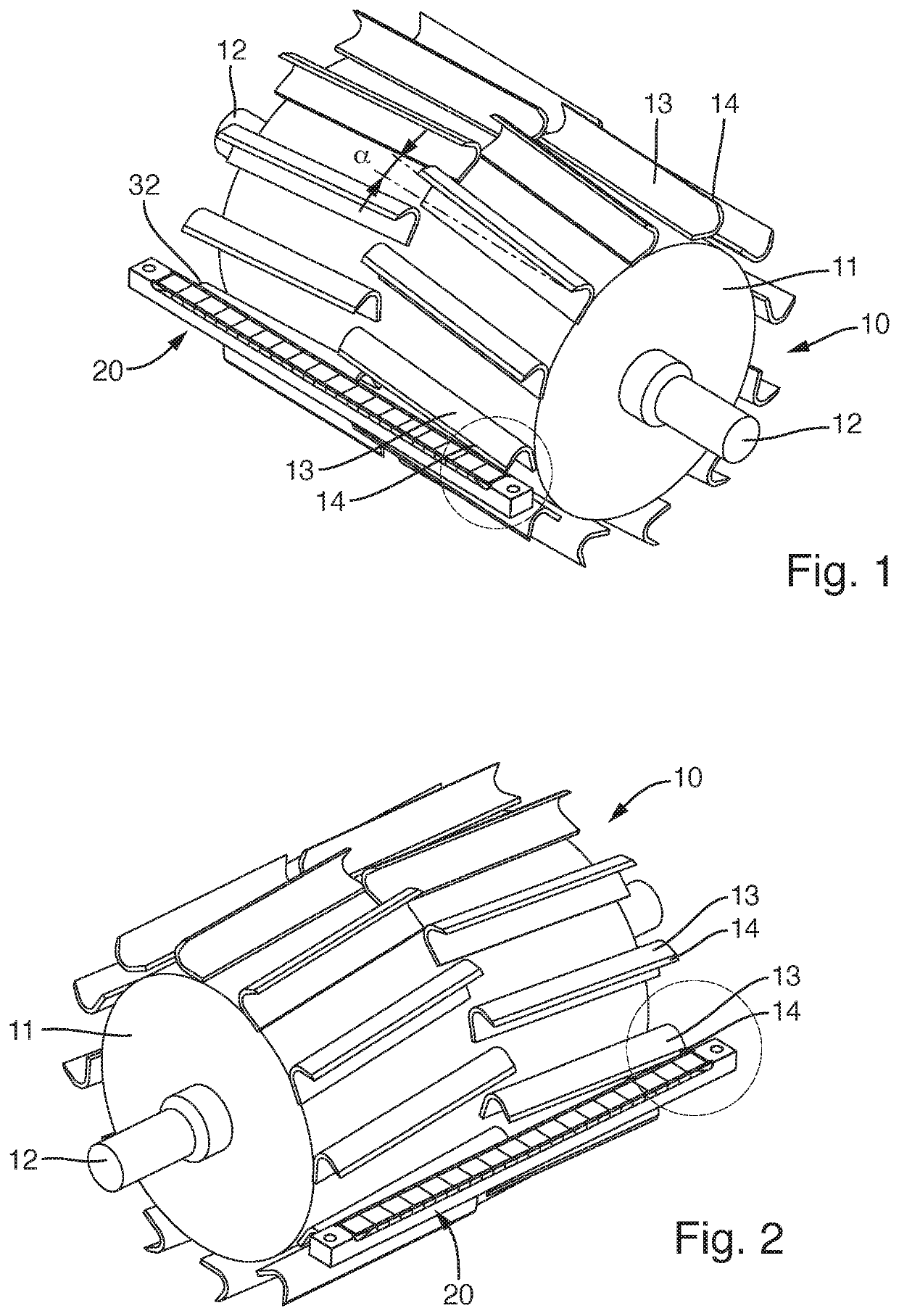
[0043]FIG. 1 shows a chopping drum 10 that comprises a roller-shaped cutting body 11. Knife bars 13 are arranged on the outer circumference of cutting body 11. Knife bars 13 each have an edge 14. Knife bars 13 are mounted on the outer circumference of cutting body 11 in such a way that they are set at a cutting angle α. Cutting angle α is formed between edge 14 and an axial line proceeding parallel to the rotation axis of chopping drum 10.

[0044]As is evident from the drawing, two rows of knife bars 13 are provided, proceeding in a circumferential direction of chopping drum 10. The arrangement of knife bars 13 is such that knife bars 13 of the one row of knife bars 13 are set in a V-shape with respect to the other row of knife bars 13. Identical cutting angles α are provided in each case. Cutting body 11 comprises, at its two longitudinal-side ends, bearing shafts 12 with which it can be held rotatably on a cutting unit.

[0045]It is further evident from FIGS. 1 and 2 that a shear bar ...


PUM


Abstract

The invention relates to a shear bar (20), in particular for a forage harvester or another agricultural or silvicultural machine, having a carrier (21) that comprises a cutting region (30); a plurality of cutting elements (31) being set alongside one another in the cutting region (30); the cutting elements (31) comprising a partial edge and at least some of the partial edges forming a cutting edge (32) that is embodied to form, with a knife bar, a cutting engagement for the material to be shredded; the cutting edge (32) forming a transition between a cutting surface (32.1) that is constituted by the cutting elements (31) and extends transversely to the cutting direction, and an exposed surface (32.2) that extends substantially in a cutting direction and indirectly or directly adjoins the cutting edge (32). A shear bar of this kind can be configured to be break-resistant with little complexity in terms of parts and manufacture if provision is made that an infeed element (34), which is embodied as a sintered part made of hard material having an infeed bevel (34.6) profiled on in the sintering process, is provided on or in the row of cutting elements (31); the infeed bevel (34.6) being carried over indirectly or directly into the cutting edge (32); and the infeed bevel (34.6) being arranged at a tilt with respect to the cutting edge (32) in such a way that it is arranged with a setback with respect to the exposed surface (32.2) and toward the cutting surface (32.1).

Description

BACKGROUND OF THE INVENTION1. Field of the Invention[0001]The invention relates to a shear bar, in particular for a forage harvester or another agricultural or silvicultural machine, having a carrier that comprises a cutting region; a plurality of cutting elements being set alongside one another in the cutting region; the cutting elements comprising a partial edge and at least some of the partial edges forming a cutting edge that is embodied to form, with a knife bar, a cutting engagement for the material to be shredded; the cutting edge forming a transition between a cutting surface that is constituted by the cutting elements and extends transversely to the cutting direction, and an exposed surface that extends substantially in a cutting direction and indirectly or directly adjoins the cutting edge.2. Description of the Prior Art[0002]EP 2 842 413 A1 (US 2015 / 0132997) discloses a forage harvester that comprises a cutting unit having a chopping drum. Knife bars are fastened on the c...

Claims


Application Information

Patent Timeline
Patent Type & Authority Applications(United States)
IPC IPC(8): A01D34/52A01F29/06B02C18/18
CPCB02C18/18A01F29/06A01D34/52B02C2018/188A01F29/09A01D43/08
Inventor ESSIG, WOLFGANGSCHNEIDER, UWESEIFRIED, FABIANROMING, JULIAN
Owner BETEK
Why Eureka
Try Eureka