
Clothes dryer

a clothes dryer and drum technology, applied in the field of clothes dryers, can solve the problems of degrading the drying performance of clothes dryers, and achieve the effects of improving the air tightness between the drum and the front support fram

Pending Publication Date: 2020-12-24
SAMSUNG ELECTRONICS CO LTD
View PDF4 Cites 1 Cited by
  • Summary
  • Abstract
  • Description
  • Claims
  • Application Information

AI Technical Summary

Benefits of technology

The patent describes using a sealing member made of an elastic material and a fabric material to improve the airtightness between a drum and its front support frame. This helps to prevent leaks and improve the overall performance of the sealing system. The sealing member forms a hollow when pressed by the drum and front support frame, creating a better seal and reducing resistance during operation. The line contact between the sealing member and the inner surface of the drum is achieved, ensuring a better connection without causing excessive resistance during contact.

Problems solved by technology

The outflow of wet vapor or lint not only degrades the drying performance of the clothes dryer, but also leads to accidents, such as fire.

Method used


Image

  • Clothes dryer
  • Clothes dryer
  • Clothes dryer

Examples


Embodiment Construction

[0038]Hereinafter, preferred embodiments of the disclosure will be described in detail with reference to the accompanying drawings. On the other hand, the terms “front end”, “rear end”, “upper part”, “lower part”, “upper end” and “lower end” used in the following description are defined based on the drawings, and the shape and position of each component is not limited by these terms.

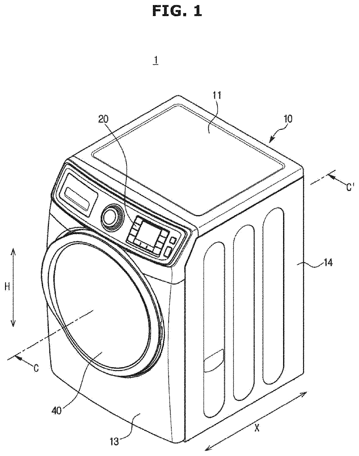
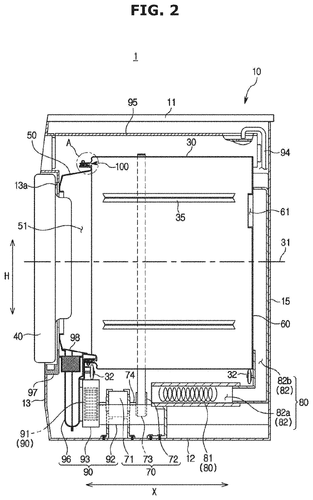
[0039]FIG. 1 is a perspective view illustrating a clothes dryer 1 according to an embodiment of the disclosure, and FIG. 2 is a cross-sectional view illustrating the clothes dryer 1 taken line along C-C′ of FIG. 1.

[0040]Referring to FIGS. 1 and 2, the clothes dryer 1 may include a cabinet 10 forming the external appearance thereof.

[0041]The cabinet 10 may have a substantially box shape. Specifically, the cabinet 10 may have a top panel 11, a bottom panel 12, a front panel 13, a left side panel (not shown), a right side panel 14, and a rear panel 15. In the present embodiment, the left side panel, the rig...


PUM


Abstract

Provided is a clothes dryer having an improved structure which allows a drying performance to be improved. The clothes dryer includes a cabinet having an inlet, a support frame having a laundry inlet corresponding to the inlet and disposed inside the cabinet, a drum rotatably disposed inside the cabinet and having an opening corresponding to the laundry inlet, and a sealing member disposed between the laundry inlet of the support frame and the opening of the drum, wherein the sealing member includes a seal body having an elastic material.

Description

TECHNICAL FIELD[0001]The disclosure relates to a clothes dryer, and more specifically, to a clothes dryer having an improved structure which allows the drying performance to be improved.BACKGROUND ART[0002]A clothes dryer, which is a home appliance for drying a wet object, dries an object by circulating heated air to pass through a drum containing the object while the drum is rotating at a low speed.[0003]The clothes dryer may include a drum rotatably installed therein, a driving device to drive the drum, a blowing device to blow air into the rotating drum, and a heater provided to heat the air.[0004]An object to be dried is s put into the drum and when the clothes dryer is operated, the drum is rotated by the operation of the driving device, and at the same time, heated air is supplied into the drum by the operations of the heater and the blowing device.[0005]The clothes dryer may further include a front support frame provided to support the drum on the front. When the airtightness...

Claims


Application Information

Patent Timeline
Patent Type & Authority Applications(United States)
IPC IPC(8): D06F58/04D06F58/20
CPCD06F58/04D06F58/20
Inventor LEE, SEUNG-MOKJANG, SAM YOUNG
Owner SAMSUNG ELECTRONICS CO LTD
Learn More