
Optical unit and endoscope

an endoscope and optical technology, applied in the field of optical units and endoscopes, can solve the problems of reducing the accuracy of the cover glass with respect to the holding tube, the difficulty of further the decrease of the air tightness. the effect of enhancing the air tightness between the holding tube and the cover glass, wide angle visual field, and accurate and close disposed

Active Publication Date: 2018-02-08
FUJIFILM CORP
View PDF0 Cites 2 Cited by
  • Summary
  • Abstract
  • Description
  • Claims
  • Application Information

AI Technical Summary

Benefits of technology

The patent aims to improve the airtightness between the holding tube and the cover glass. It suggests that it is not enough to only pour a melted joining member between the side surface of the cover glass and the inner peripheral surface of the holding tube. The patent proposes additional measures to enhance the seal, such as using a more advanced joining process or adding a sealant between the two surfaces. These measures may improve the efficiency and reliability of the holding tube-cover glass assembly in various applications such as electron microscopes or lighting devices.

Problems solved by technology

Therefore, the optical unit of JP2000-139821A and JP2000-217775A has a problem that it is difficult to further enhance the airtightness between the holding tube and the cover glass.
Therefore, there is a problem that the attachment accuracy of the cover glass with respect to the holding tube decreases and the airtightness decreases.
In this case, there also is a problem that the joining member poured into the solder pool part flows into the distal end surface of the optical lens.

Method used


Image

  • Optical unit and endoscope
  • Optical unit and endoscope
  • Optical unit and endoscope

Examples


first embodiment

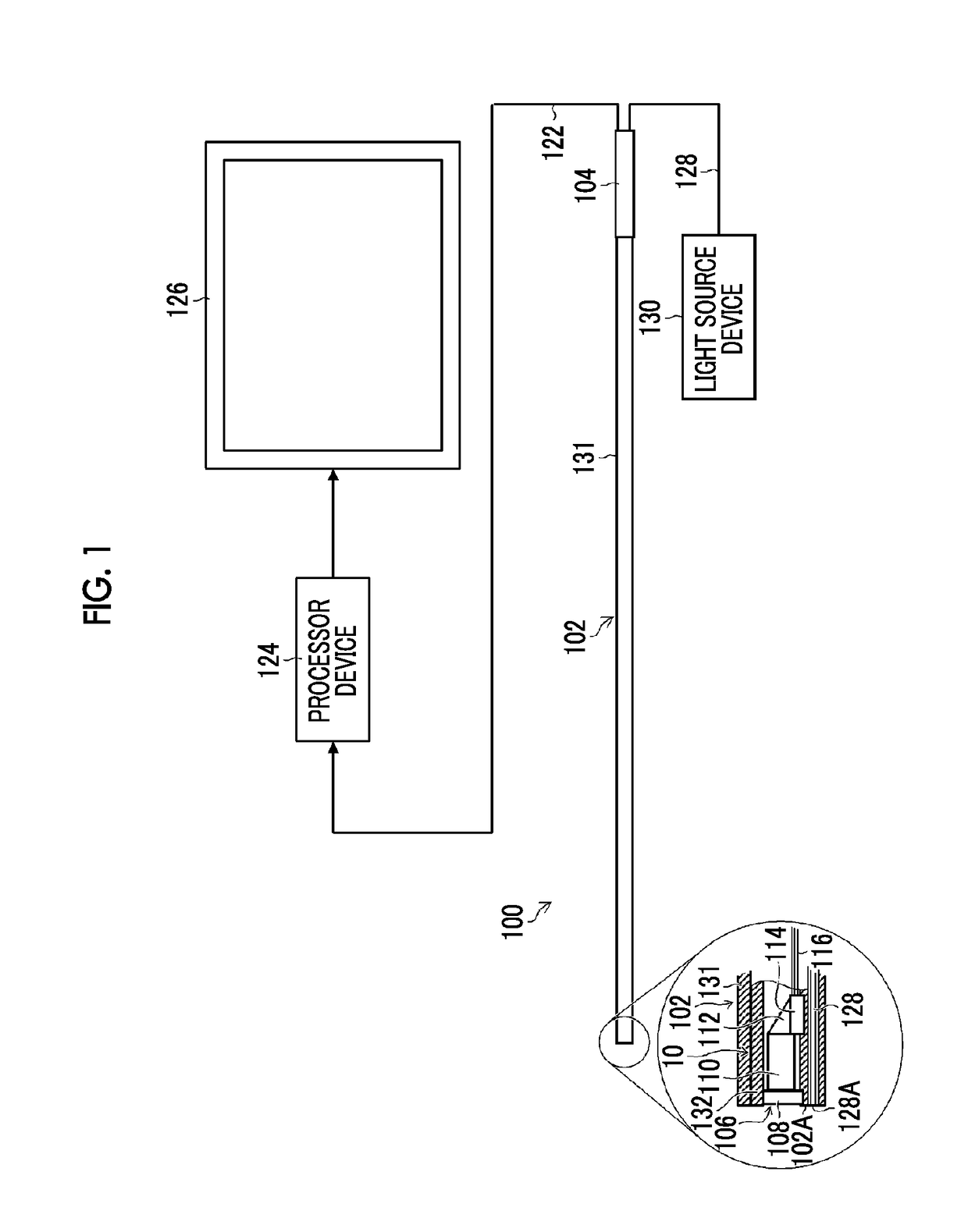
[0057][Endoscope 100]FIG. 1 is a configuration view of an endoscope 100 of an embodiment provided with an optical unit 10 of a first embodiment, and illustrates a direct viewing type hard endoscope, such as a laparoscope, as the endoscope 100.

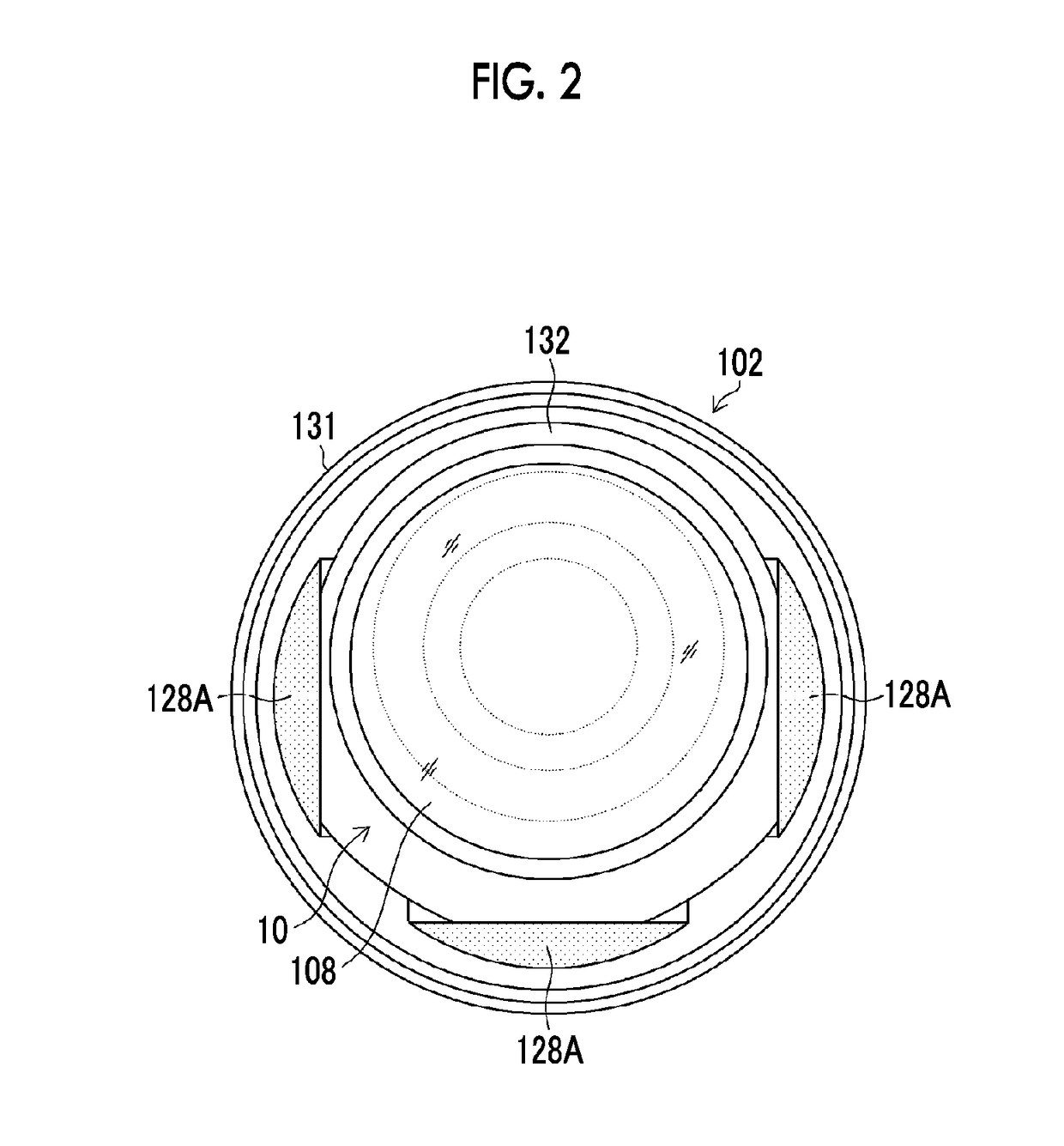
[0058]The endoscope 100 includes a cylindrical insertion part 102 inserted into a patient's body, and a cylindrical operating part 104 connected to a proximal end of the insertion part 102. FIG. 2 is a front view of a distal end surface 102A of the insertion part 102.

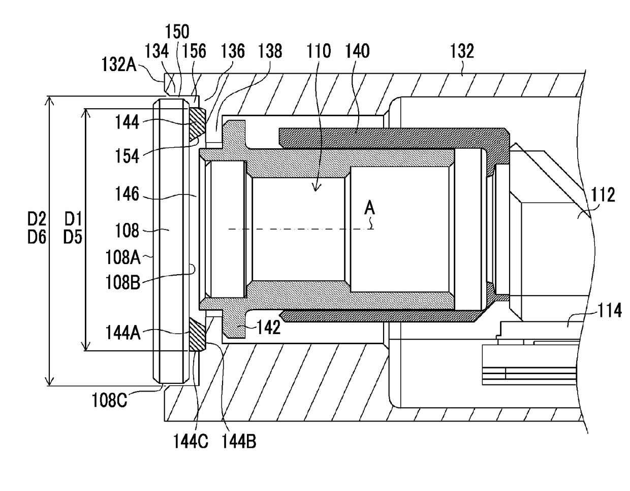
[0059]As illustrated in FIGS. 1 and 2, a cover glass 108, which constitutes a distal end of an optical member 106, is disposed on the distal end surface 102A of the insertion part 102. Additionally, as illustrated in an enlarged cross-sectional view of some main parts in FIG. 1, an optical lens 110, which constitutes a main body of the optical member 106, and a prism 112 are built inside the insertion part 102. Additionally, an imaging device 114, which picks up an observation imag...

second embodiment

[0098][Optical unit 170 of Second Embodiment]

[0099]FIG. 6 is an enlarged cross-sectional view of main parts of illustrating the configuration of an optical unit 170 of a second embodiment. In addition, in a case where the optical unit 170 is described, members, which are the same as or similar to those of the optical unit 10 illustrated in FIGS. 1 to 5, will be designated by the same reference signs, and the description thereof will be omitted.

[0100]A holding tube 172 of the optical unit 170 includes a third recess 180 that has a third inner wall surface 174 and a third bottom surface 176 and that accommodates the cover glass 108 and a spacer 178.

[0101]The third inner wall surface 174 is provided at a position that faces the side surface 108C of the cover glass 108, and has the cover glass fixing part 134. The third bottom surface 176 is provided at a position that faces the second end surface 178B of the spacer 178, and has the cover glass position restricting part 136.

[0102]The sp...


PUM

PropertyMeasurementUnit
reflectivityaaaaaaaaaa
angleaaaaaaaaaa
opening angleaaaaaaaaaa

Abstract

Provided are an optical unit and an endoscope that can enhance the airtightness between a holding tube and a cover glass without a joining member flowing into a distal end surface of an optical lens while maintaining the attachment accuracy of the cover glass. A spacer is disposed between a cover glass position restricting part of a holding tube of an optical unit and a cover glass. The position of the cover glass in an optical axis is restricted by the cover glass position restricting part via a spacer. An external diameter of a first end surface of the spacer is smaller than an internal diameter of a cover glass fixing part of the holding tube. A solder pool part is provided in a region, which is surrounded by a side surface of the spacer, the cover glass fixing part, and the cover glass position restricting part.

Description

CROSS-REFERENCE TO RELATED APPLICATIONS[0001]This application is a Continuation of PCT International Application No. PCT / JP2016 / 058007 filed on Mar. 14, 2016, which claims priority under 35 U.S.C. § 119(a) to Japanese Patent Application No. 2015-071818 filed on Mar. 31, 2015. Each of the above applications is hereby expressly incorporated by reference, in their entirety, into the present application.BACKGROUND OF THE INVENTION1. Field of the Invention[0002]The present invention relates to an optical unit and an endoscope, and particularly, to an optical unit and an endoscope including a cover glass and an optical lens disposed at a distal end of an insertion part of the endoscope.2. Description of the Related Art[0003]As disclosed in JP2000-139821A and JP2000-217775A, an optical unit having a cover glass and an optical lens is provided at a distal end of an insertion part of an endoscope, and an image of an affected area, which enters an incidence surface of the cover glass and leav...

Claims


Application Information

Patent Timeline
Patent Type & Authority Applications(United States)
IPC IPC(8): G02B23/24A61B1/00A61B1/04
CPCG02B23/2423A61B1/04A61B1/00163G02B23/2476G02B1/11G02B23/24A61B1/00096
Inventor YAMADA, HIDEYUKI
Owner FUJIFILM CORP
Learn More