Device for cellular electrophysiology sensor, cellular electrophysiology sensor using the device, and method for manufacturing the cellular electrophysiology sensor device

a sensor and cellular electrophysiology technology, applied in the field of cellular electrophysiology sensor devices, can solve the problems of unevenness and peeling easily in joining, the technique requires a skilled operator, and the application that requires high-throughput measurement cannot be suitable for high-throughput measurement, so as to reduce leakage current, improve the air tightness between the side surface of the sensor chip and the chip holding part, and strengthen the effect of joining

Active Publication Date: 2013-05-21
PANASONIC CORP
View PDF51 Cites 0 Cited by
  • Summary
  • Abstract
  • Description
  • Claims
  • Application Information

AI Technical Summary

Benefits of technology

[0015]The present invention reduces a leakage current on a side surface of a sensor chip.
[0017]Thus, the present invention can reduce a leakage current on the side surface of the sensor chip.
[0018]The reason therefor is because the airtightness between the side surface of the sensor chip and the chip holding part is increased. That is to say, since the sensor chip made of silicon and the chip holding part made of glass are adhesively bonded to each other, the side surface of the sensor chip and the chip holding part can be brought into close contact with each other, and thus the joining is strengthened.
[0019]Therefore, the airtightness between the side surface of the sensor chip and the chip holding part is increased, resulting in reducing a leakage current.

Problems solved by technology

However, on the other hand, since the patch clamp technique as a measuring technique requires an extremely high skill of inserting a fine micropipette into a single cell with a high accuracy, this technique requires a skilled operator.
Therefore, this technique is not suitable for an application that requires high-throughput measurement.
That is to say, when sensor chip 102 is joined to the chip holding part with an adhesive agent, unevenness and peeling easily occur in joining.
As a result, a leakage current tends to occur.

Method used


Image

  • Device for cellular electrophysiology sensor, cellular electrophysiology sensor using the device, and method for manufacturing the cellular electrophysiology sensor device
  • Device for cellular electrophysiology sensor, cellular electrophysiology sensor using the device, and method for manufacturing the cellular electrophysiology sensor device
  • Device for cellular electrophysiology sensor, cellular electrophysiology sensor using the device, and method for manufacturing the cellular electrophysiology sensor device

Examples


first exemplary embodiment

[0068](First Exemplary Embodiment)

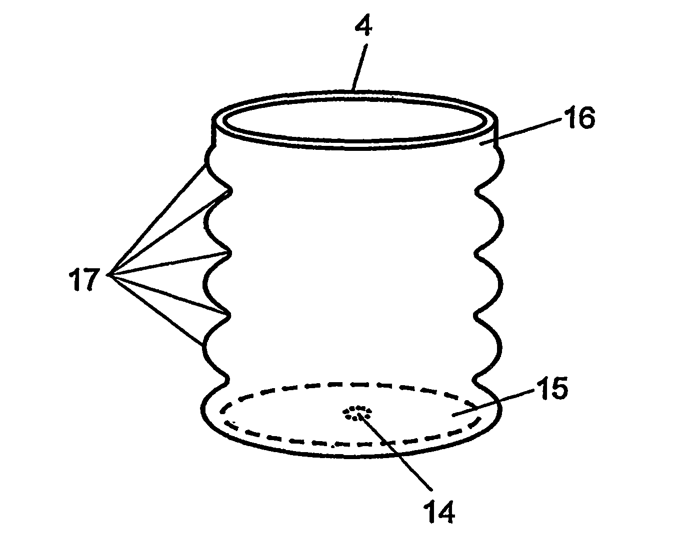
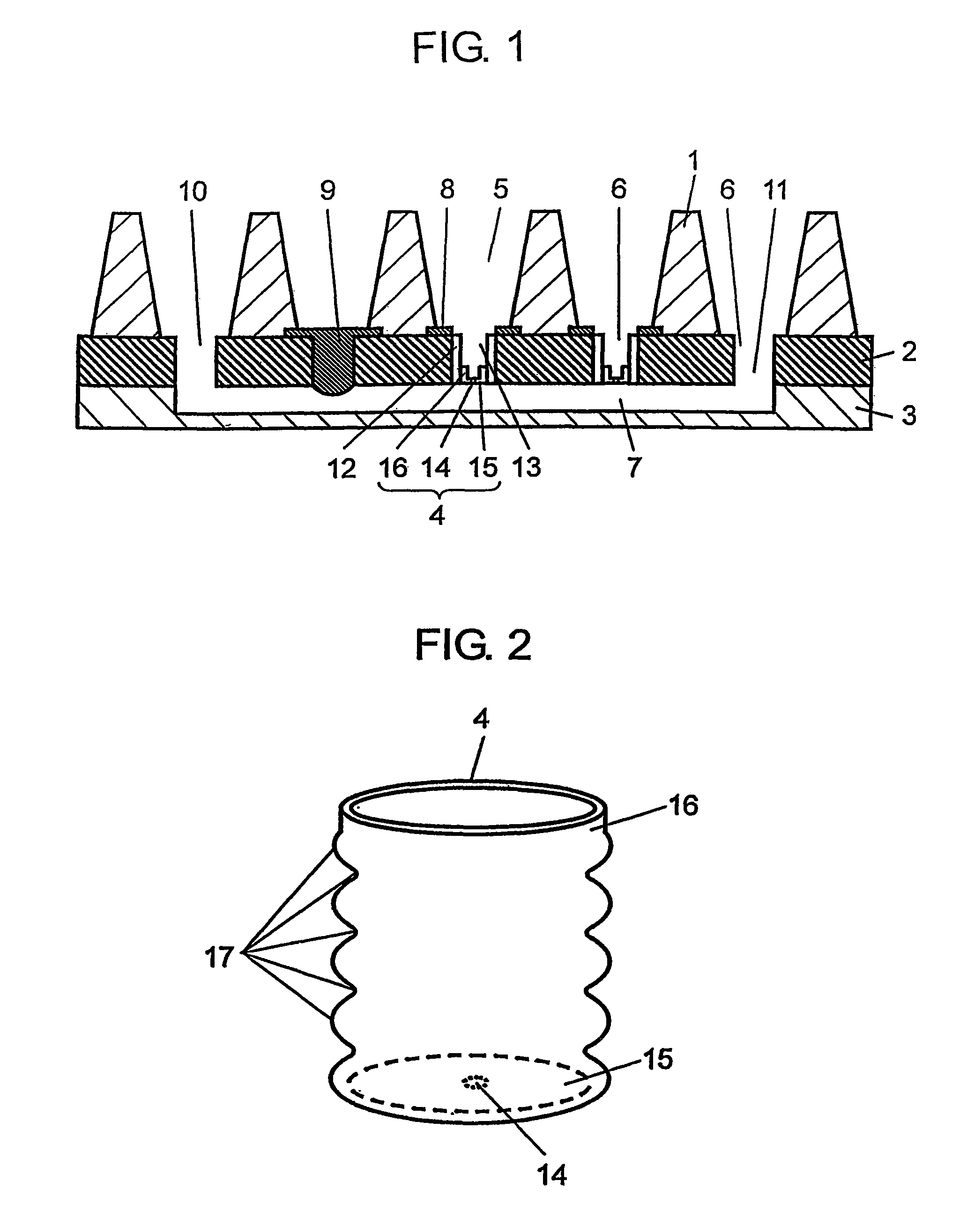
[0069]FIG. 1 is a sectional view showing a cell electrophysiological sensor in accordance with a first exemplary embodiment of the present invention.

[0070]As shown in FIG. 1, the cell electrophysiological sensor in accordance with the first exemplary embodiment includes well plate 1, holding plate 2 that is brought into contact with the lower part of well plate 1, and flow passage plate 3 that is brought into contact with the lower part of holding plate 2. The below mentioned sensor chip 4 is mounted on holding plate 2.

[0071]Through hole 5 formed in well plate 1, through hole 6 formed in holding plate 2 and hollow space as flow passage 7 formed in flow passage plate 3 communicate with each other.

[0072]Furthermore, through hole 5 of well plate 1 functions as an electrolytic bath and can store an electrolytic solution such as extracellular fluid Furthermore, flow passage 7 of flow passage plate 3 also functions as an electrolytic bath and can store an...

second exemplary embodiment

[0159](Second Exemplary Embodiment)

[0160]FIG. 8 is a partial sectional view showing a cell electrophysiological sensor in accordance with a second exemplary embodiment of the present invention. The same reference numerals are given to the same configurations as in the first exemplary embodiment and the description thereof is omitted herein.

[0161]The second exemplary embodiment is different from the first exemplary embodiment in that hydrophilic film 30 is formed on the outer surface of sensor chip 4 by a thin film process in the second exemplary embodiment as shown in FIG. 8. In the second exemplary embodiment, hydrophilic film 30 is made of silicon dioxide.

[0162]Then, a method for forming hydrophilic film 30 includes a thin film process such as a method of thermally oxidizing the outer side surface of sensor chip 4, or a method of sputtering silicon dioxide, a CVD method, or the like. Then, by forming a film by using this thin film process, for example, hydrophilic film 30 having a...

third exemplary embodiment

[0167](Third Exemplary Embodiment)

[0168]FIG. 9 is a partial sectional view showing a cell electrophysiological sensor in accordance with a third exemplary embodiment of the present invention. The same reference numerals are given to the same configurations as in the first and second exemplary embodiments and the description thereof is omitted herein.

[0169]The third exemplary embodiment is different from the first exemplary embodiment in that cylindrical-shaped chip holding part 12 of the third exemplary embodiment is longer than chip holding part 12 of the first exemplary embodiment and furthermore sensor chip 4 is disposed at the top end thereof, and chip holding part 12 is inserted into opening 32 of socket 31 as shown in FIG. 9. Furthermore, electrode 9 at the lower part is inserted into opening 32 of socket 31.

[0170]That is to say, in the third exemplary embodiment, unlike the structure of the first exemplary embodiment in which the plurality of sensor chips 4 share one flow pas...


PUM

PropertyMeasurementUnit
glass softening pointaaaaaaaaaa
contact angleaaaaaaaaaa

Abstract

A leakage current on a side surface of a sensor chip of a cell electrophysiological sensor is reduced. In order to do so, a sensor chip having a continuity hole and a chip holding part covering the side surface of the sensor chip are provided. The sensor chip includes silicon as a main component, and the chip holding part is made of glass. The chip holding part is adhesively bonded to the side surface of the sensor chip by glass welding. Thus, in the cell electrophysiological sensor device of the present invention, the airtightness between the side surface of the sensor chip and the chip holding part is improved, so that a leakage current can be reduced.

Description

[0001]This application is a U.S. NATIONAL PHASE APPLICATION OF PCT INTERNATIONAL APPLICATION PCT / JP2007 / 062887.TECHNICAL FIELD[0002]The present invention relates to a cell electrophysiological sensor device for measuring a cell electrophysiological phenomenon such as intracellular potential or extracellular potential, which is used for measuring physico-chemical change generated by cellular activities; a cell electrophysiological sensor using the same; and a method for manufacturing a cell electrophysiological sensor device.BACKGROUND ART[0003]A patch clamp technique in electrophysiology is known as a method for measuring an ion channel which the cell membrane possesses. With this patch clamp technique, various functions of the ion channel have been elucidated. The function of the ion channel has been a great interest and applied to development of drugs.[0004]However, on the other hand, since the patch clamp technique as a measuring technique requires an extremely high skill of inse...

Claims


Application Information

Patent Timeline
Patent Type & Authority Patents(United States)
IPC IPC(8): C12M1/34
CPCG01N33/48728
Inventor USHIO, HIROSHINAKATANI, MASAYAHIRAOKA, SOICHIROOSHIMA, AKIYOSHITAKAHASHI, MAKOTO
Owner PANASONIC CORP
Why Eureka
Try Eureka