
Data buffer and data buffer control

a data buffer and control technology, applied in the field of data buffers and data buffer control, can solve the problems of discontinuities in the output data stream, noise and/or distortion,

Active Publication Date: 2020-12-24
SONY CORP
View PDF0 Cites 0 Cited by
  • Summary
  • Abstract
  • Description
  • Claims
  • Application Information

AI Technical Summary

Benefits of technology

The patent text discusses a method for controlling data buffers, specifically for audio and video data. The technical effect of this patent is to provide a way to handle rate discrepancies between the rate at which data is written to the buffer and the rate at which data is read from the buffer, without causing discontinuities in the output data stream. This is achieved by detecting the difference between the buffer occupancy and a target buffer occupancy, and adjusting the buffer occupancy to match the difference. This allows for a more precise adjustment of the buffer occupancy, reducing the likelihood of data overflow or underflow. The method can be applied to a variety of data buffer arrangements and can be used for any sample-based data for which inter-sample interpolation provides a meaningful outcome.

Problems solved by technology

However, such a coarse adjustment can give rise to discontinuities in the output data stream, which can be a particular problem if the data items represent, for example, audio samples.
Another approach is interpolation amongst output data items, but this can also give rise to noise and / or distortion.

Method used


Image

  • Data buffer and data buffer control
  • Data buffer and data buffer control
  • Data buffer and data buffer control

Examples


Embodiment Construction

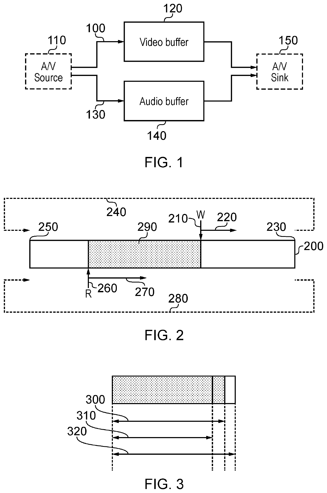
[0023]Referring to the drawings, FIG. 1 schematically illustrates a video and audio buffer arrangement in which video data 100 from an audio / video (A / V) source 110 is buffered by a video buffer 120 and audio data 130 from the A / V source is buffered by an audio buffer 140, before both the audio and video data are supplied from the respective buffers to an A / V sink 150.

[0024]Different respective buffers are used for the video and audio data, in part because of differences in properties of these types of data. For example, in order to deal with a video buffer becoming either too full or insufficiently full, for example because of data rate discrepancies between the rate at which data is written to the buffer and the rate at which data is read from the buffer, it is generally necessary to skip a video frame or repeat a video frame, because temporal interpolation between video frames for rate conversion is relatively processor-intensive and can degrade the video quality. In contrast, for...


PUM


Abstract

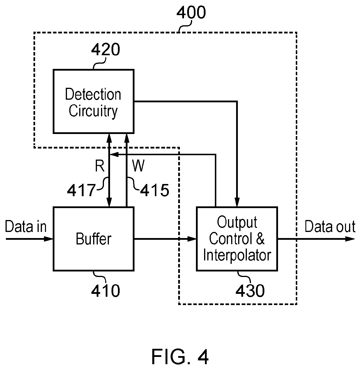
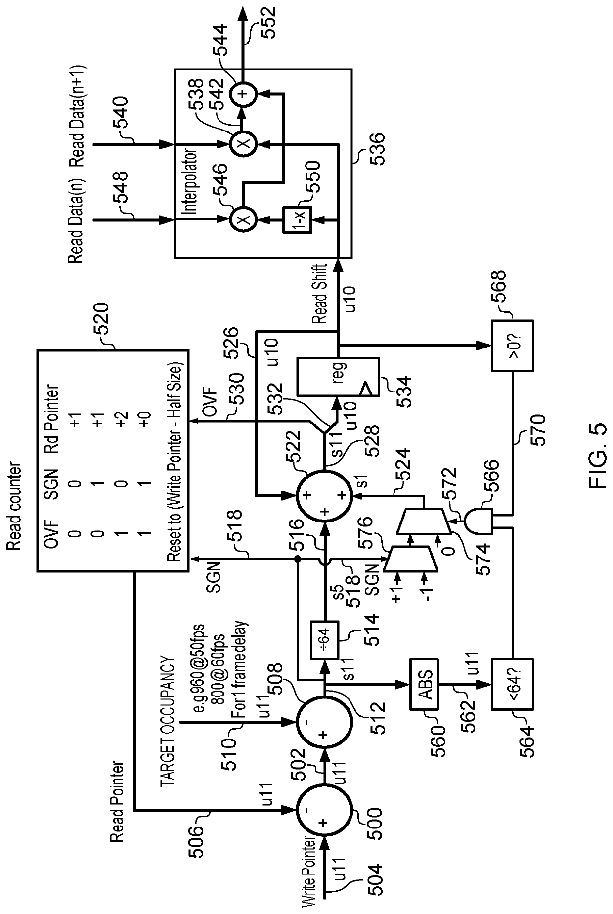
Control apparatus to control operation of a data buffer to which data items are written according to a write pointer which advances in position in response to an input data item rate and from which data items are read according to a read pointer which advances in position in response to an output data item rate, comprises: a detector configured to detect an occupancy difference between a current buffer occupancy and a target buffer occupancy, in which the current buffer occupancy represents a difference between the read and write pointers; an output data item interpolator configured to interpolate a data item at an interpolated data buffer location displaced by a read offset displacement from a data buffer location pointed to by the read pointer; and output control circuitry configured, in response to a current occupancy difference exceeding a threshold occupancy difference, to change the read pointer from an initial read pointer to a target read pointer by a change amount so as to reduce the occupancy difference, the output control circuitry being configured to progressively vary the read offset displacement so as to define an interpolated data buffer location which progresses over the output of a transitional group of data items towards the location pointed to by the target read pointer; the output control circuitry being further configured, when the occupancy difference is less than the threshold occupancy difference and the interpolated data buffer location is aligned with the target read pointer, to inhibit operation of the output data item interpolator and to control output of an output data item from the data buffer location pointed to by the read pointer.

Description

BACKGROUNDField of the Disclosure[0001]This disclosure relates to data buffers and data buffer control.Description of the Prior Art[0002]In the context of a data buffer such as an audio buffer to which data items are written according to a write pointer which advances in position in response to an input data item rate and from which data items are read according to a read pointer which advances in position in response to an output data item rate, current buffer occupancy represents a difference between the read and write pointers.[0003]To avoid data overflow or underflow, a target buffer occupancy may be specified, an occupancy difference between a current buffer occupancy and a target buffer occupancy can be detected. In response to the occupancy difference exceeding a threshold, it is possible to drop or repeat output data items from the data buffer. However, such a coarse adjustment can give rise to discontinuities in the output data stream, which can be a particular problem if t...

Claims


Application Information

Patent Timeline
IPC IPC(8): G11B20/10H04N21/44H04N21/439
CPCH04N21/44004G11B20/10527H04N21/4392G11B2020/10712H04J3/0632H04L7/0029G06F5/06G11B2020/10666H04L49/90
Inventor KEATING, STEPHEN MARK
Owner SONY CORP
Learn More