Control circuit module, electronic component connection structure, and power conversion device

a technology of electronic components and control circuits, which is applied in the direction of printed circuit non-printed electric components, instruments, final product manufacture, etc., can solve the problems of reducing the power conversion efficiency of the dc-dc converter, affecting the operation of the dc-dc converter, and the parasitic inductance will increase by a corresponding amount, so as to reduce the power conversion efficiency of the power conversion device, the effect of preventing the degradation of the power conversion efficiency

Inactive Publication Date: 2020-12-24
MURATA MFG CO LTD
View PDF0 Cites 0 Cited by
  • Summary
  • Abstract
  • Description
  • Claims
  • Application Information

AI Technical Summary

Benefits of technology

The present invention provides control circuit modules, electronic component connection structures, and power conversion devices that are able to prevent degradation of power conversion efficiency. The technical effects of this invention include minimizing parasitic inductance, reducing or preventing degradation of power conversion efficiency, and optimizing power conversion device performance.

Problems solved by technology

However, in the DC-DC converter disclosed in Japanese Unexamined Patent Application Publication No. 2013-005578, since the inductor and the control IC are electrically connected to each other via the wiring line portion of the mounting substrate, a parasitic inductance generated by the wiring line portion may affect the operation of the DC-DC converter.
In particular, as the length of the wiring line portion interposed between the inductor and the control IC increases, the parasitic inductance will increase by a corresponding amount and may be a factor in reducing the power conversion efficiency of the DC-DC converter.

Method used


Image

  • Control circuit module, electronic component connection structure, and power conversion device
  • Control circuit module, electronic component connection structure, and power conversion device
  • Control circuit module, electronic component connection structure, and power conversion device

Examples


Embodiment Construction

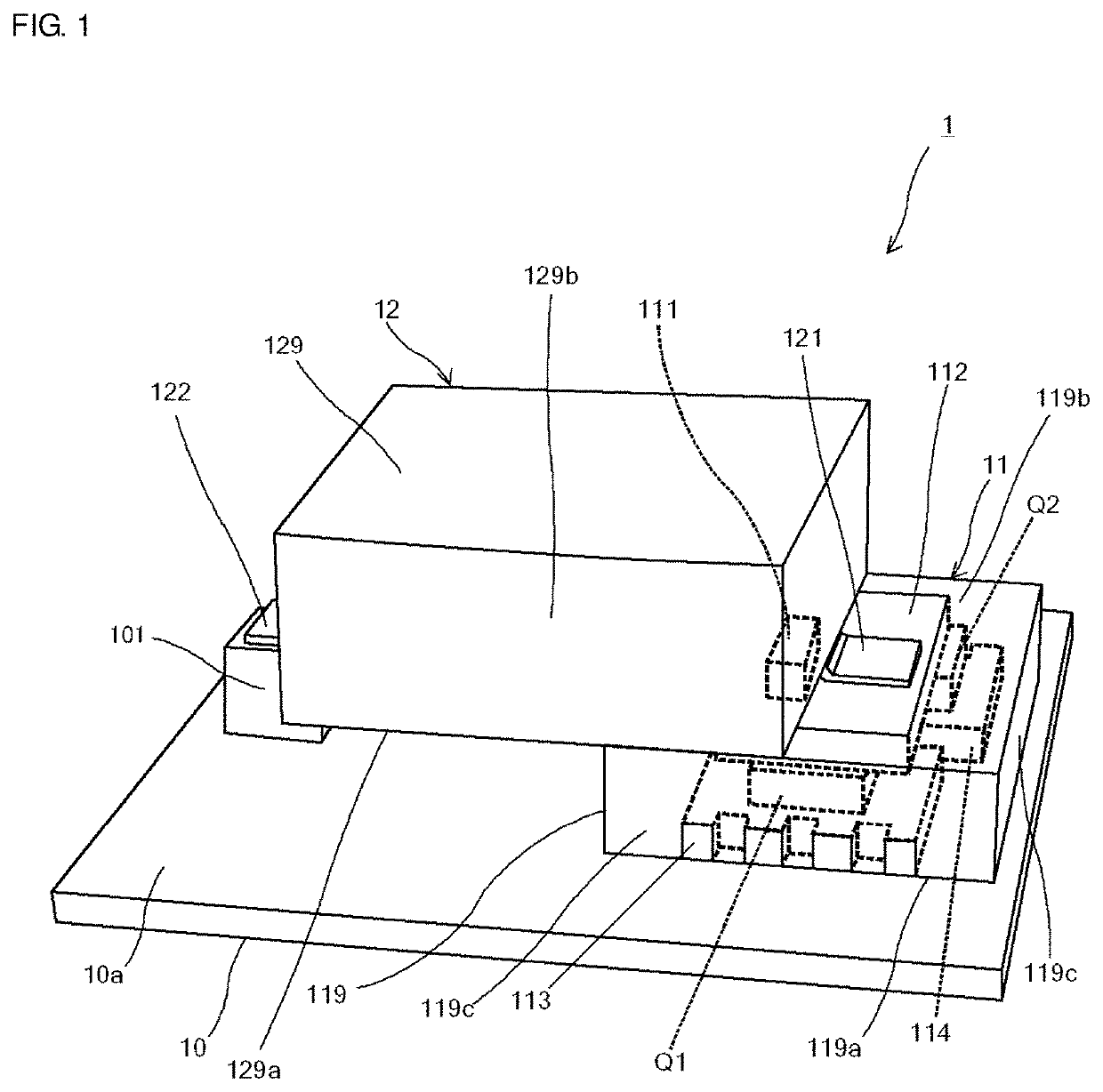
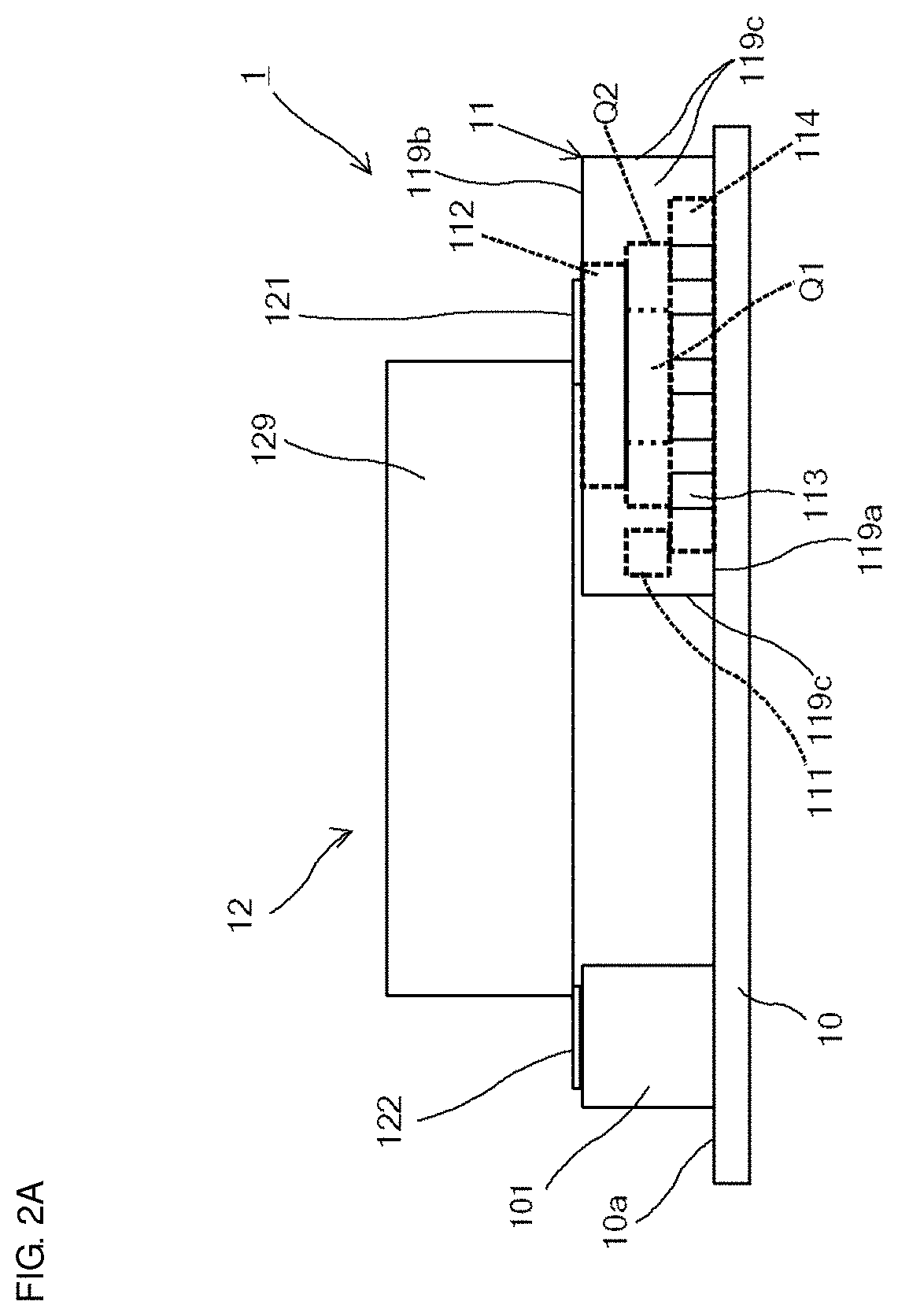
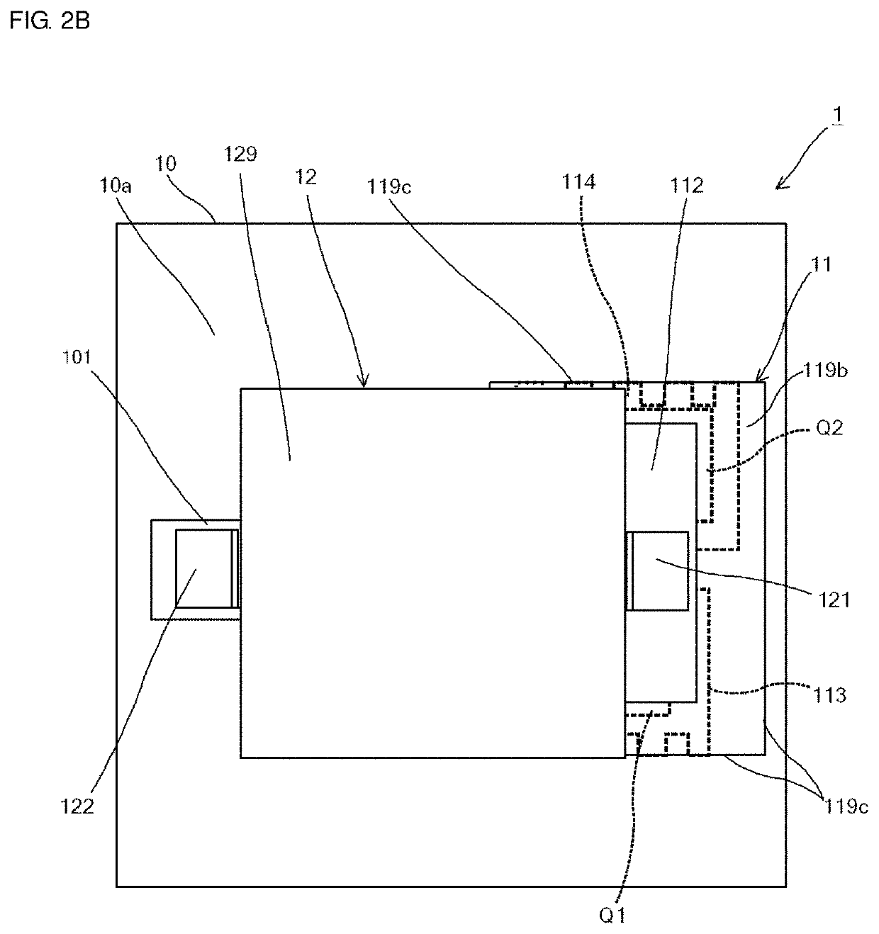
[0020]Hereafter, preferred embodiments of the present invention will be described in detail while referring to the drawings. A power conversion device according to a preferred embodiment of the present invention includes an inductor element including a lead frame and a control circuit module including two switching elements and a control circuit. The control circuit module includes a package including a first surface that faces a substrate and a second surface that faces the opposite side from the substrate when the control circuit module is mounted on the substrate, a first electrode that is provided in the package so as to be exposed from the first surface of the package, and a second electrode that is commonly connected to one input / output terminal of each of the two switching elements and is exposed from the second surface of the package. The lead frame of the inductor element contacts the second electrode of the control circuit module. As a result of the power conversion device...


PUM


Abstract

A control circuit module includes FETs each including a control terminal, an input terminal, and an output terminal, a control circuit connected to the control terminals and controlling on / off operations of the FETs by outputting a control signal to the control terminals, a first package including the FETs and the control circuit provided therein and including a first surface, a second surface, and a third surface, which is a side surface perpendicular or substantially perpendicular to the first surface and the second surface, first electrodes provided in the first package and exposed from the first surface of the first package, and a second electrode that is provided in the first package and exposed from the second surface of the first package.

Description

CROSS REFERENCE TO RELATED APPLICATIONS[0001]This application claims the benefit of priority to Japanese Patent Application No. 2018-050332 filed on Mar. 19, 2018 and is a Continuation Application of PCT Application No. PCT / JP2019 / 000165 filed on Jan. 8, 2019. The entire contents of each application are hereby incorporated herein by reference.BACKGROUND OF THE INVENTION1. Field of the Invention[0002]The present invention relates to a control circuit module, an electronic component connection structure, and a power conversion device.2. Description of the Related Art[0003]A DC-DC converter has been proposed that includes an LC module, a control IC, and a mounting substrate on which the LC module and the control IC are mounted (for example, refer to Japanese Unexamined Patent Application Publication No. 2013-005578). In this case, the LC module is formed by mounting an inductor having a choke coil formed therein on a capacitor array having a plurality of capacitors formed therein and i...

Claims


Application Information

Patent Timeline
Patent Type & Authority Applications(United States)
IPC IPC(8): H02M3/158G05F1/59H05K1/18
CPCH02M3/158G05F1/59H05K1/181H05K2201/10166H05K2201/1003H05K2201/10515H05K2201/1053H05K2201/10636H02M3/003Y02P70/50
Inventor TANGE, TAKAYUKIMIYASHITA, MUNETAKETAMURA, YUJIYOSHINAKA, TATSUYAHASHI, HIDEAKI
Owner MURATA MFG CO LTD
Why Eureka
Try Eureka