Multiplexer, radio-frequency front-end circuit, and communication device

a radio frequency front-end circuit and multi-channel technology, applied in the direction of frequency-division multiplex details, amplifier types, dual/triple band amplifiers, etc., can solve the problems of the rayleigh wave response of the acoustic wave resonator, the degradation of the insertion loss of the different bandpass filter, etc., to reduce the insertion loss and prevent the degradation of the insertion loss.

Active Publication Date: 2022-06-28
MURATA MFG CO LTD
View PDF16 Cites 0 Cited by
  • Summary
  • Abstract
  • Description
  • Claims
  • Application Information

AI Technical Summary

Benefits of technology

[0006]Preferred embodiments of the present invention provide multiplexers, radio-frequency front-end circuits, and communication devices which are each able to significantly reduce or prevent degradation of the insertion loss in the pass band which is caused by the Rayleigh wave responses of acoustic-wave resonators.

Problems solved by technology

However, as in Japanese Unexamined Patent Application Publication No. 2013-81068, a bandpass filter, which is included in a branching filter and which uses leaky waves as principal acoustic waves, has a problem about the Rayleigh wave responses of the acoustic-wave resonators.
The Rayleigh wave responses, which are produced in the pass band of a different bandpass filter, of the acoustic-wave resonators in a bandpass filter cause a problem of occurrence of a ripple in the pass band of the different bandpass filter and degradation of the insertion loss of the different bandpass filter.

Method used


Image

  • Multiplexer, radio-frequency front-end circuit, and communication device
  • Multiplexer, radio-frequency front-end circuit, and communication device
  • Multiplexer, radio-frequency front-end circuit, and communication device

Examples


first preferred embodiment

1. Basic Configuration of a Multiplexer

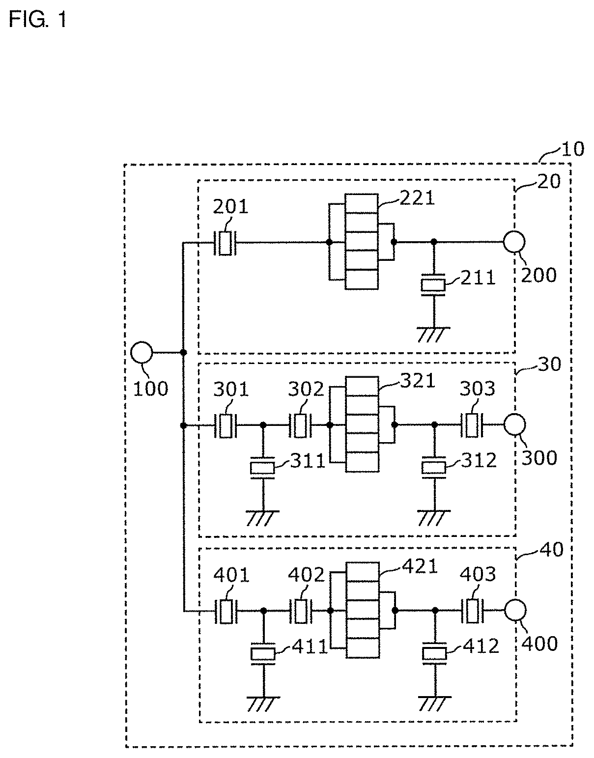
[0049]FIG. 1 is a diagram showing the configuration of a multiplexer 10 according to a first preferred embodiment of the present invention. The multiplexer 10 is a triplexer (branching filter) which includes multiple filters (in this example, three filters 20, 30, and 40), whose pass bands are different from each other, and in which the antenna-side terminals of the filters are connected to a common terminal 100. Specifically, as shown in FIG. 1, the multiplexer 10 includes the common terminal 100, three individual terminals 200, 300, and 400, and the three filters 20, 30, and 40.

[0050]The common terminal 100 is provided for the three filters 20, 30, and 40 in common, and is connected to the filters 20, 30, and 40 in the multiplexer 10. In addition, the common terminal 100 is connected to an antenna (not shown) outside the multiplexer 10. That is, the common terminal 100 also defines and functions as an antenna terminal of the multiplexer 10.

[0...

second preferred embodiment

[0115]The multiplexer according to the first preferred embodiment may be applied to a radio-frequency front-end circuit and further to a communication device including the radio-frequency front-end circuit. In a second preferred embodiment of the present invention, such a radio-frequency front-end circuit and such a communication device are described.

[0116]FIG. 8 is a diagram showing the configuration of a radio-frequency front-end circuit 3 and a communication device 1 according to the second preferred embodiment. FIG. 8 also shows components (an antenna device 2, an RF signal processing circuit (RFIC) 70, and a baseband signal processing circuit (BBIC) 80) connected to the radio-frequency front-end circuit 3. The radio-frequency front-end circuit 3, the RF signal processing circuit 70, and the baseband signal processing circuit 80 define the communication device 1.

[0117]The radio-frequency front-end circuit 3 includes the multiplexer 10 according to the first preferred embodiment,...


PUM


Abstract

A multiplexer includes a filter located between a common terminal and an individual terminal, and a filter that is located between the common terminal and an individual terminal and that has a pass band whose frequency is lower than the pass band of the filter. The filter includes serial arm resonators provided on the first path connecting the common terminal to the individual terminal. Each of the serial arm resonators includes a piezoelectric substrate and an IDT electrode which use leaky waves as principal acoustic waves. The occurrence frequency of the Rayleigh wave response of the serial arm resonator is different from that of the serial arm resonator.

Description

CROSS REFERENCE TO RELATED APPLICATIONS[0001]This application claims the benefit of priority to Japanese Patent Application No. 2017-096566 filed on May 15, 2017 and is a Continuation Application of PCT Application No. PCT / JP2018 / 018019 filed on May 9, 2018. The entire contents of each application are hereby incorporated herein by reference.BACKGROUND OF THE INVENTION1. Field of the Invention[0002]The present invention relates to a multiplexer, a radio-frequency front-end circuit, and a communication device.2. Description of the Related Art[0003]In recent years, to be compatible with a technique of using multiple frequency bands and multiple wireless systems in a single terminal, that is, a technique for multi-band and multi-mode, communication devices such as cellular phone terminals have used a multiplexer (branching filter) that separates (branches) a radio frequency signal into frequency bands.[0004]Japanese Unexamined Patent Application Publication No. 2013-81068 discloses a on...

Claims


Application Information

Patent Timeline
Patent Type & Authority Patents(United States)
IPC IPC(8): H03H9/64H03F3/19H03H9/145H03H9/72H04B1/00H04J1/10
CPCH03H9/6489H03F3/19H03H9/145H03H9/72H04B1/0067H04J1/10H03F2200/451H03F2200/111H03F1/56H03F2200/222H03H9/02826H03H9/14541H03H9/02834H03H9/02866H03H9/6496H03H9/14544
Inventor TAKAMIYA, MIKI
Owner MURATA MFG CO LTD
Why Eureka
Try Eureka