Multiplexer

a multi-channel filter and filter circuit technology, applied in the field of multi-channel filters, to achieve the effect of improving isolation characteristics, reducing or preventing degradation of insertion characteristics, and improving isolation between the first filter circuit and the second filter circui

Active Publication Date: 2020-11-17
MURATA MFG CO LTD
View PDF7 Cites 0 Cited by
  • Summary
  • Abstract
  • Description
  • Claims
  • Application Information

AI Technical Summary

Benefits of technology

[0006]Preferred embodiments of the present invention provide multiplexers that reduce or prevent degradation of insertion characteristics and that have improved isolation characteristics both in the transmission band and in the reception band.

Problems solved by technology

However, it is difficult for the duplexer disclosed in Japanese Unexamined Patent Application Publication No. 2013-118611 to improve the isolation characteristics of the duplexer both in a transmission band and in a reception band without increasing an insertion loss when the cancel circuit includes the longitudinally-coupled elastic wave resonator.

Method used


Image

  • Multiplexer
  • Multiplexer
  • Multiplexer

Examples


first preferred embodiment

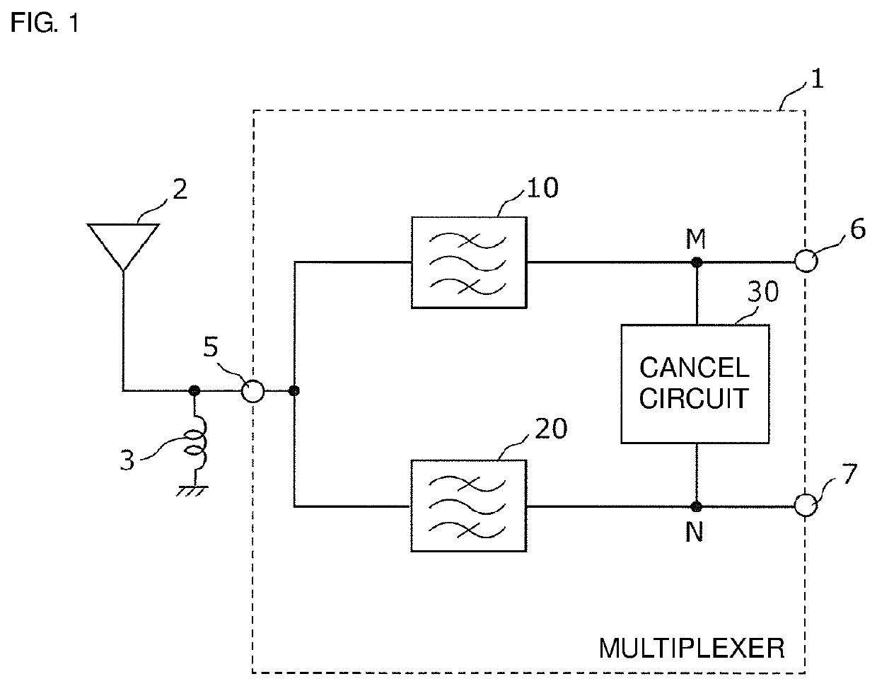
[0038]FIG. 1 is a circuit diagram of a multiplexer 1 according to a first preferred embodiment of the present invention and a peripheral circuit thereof. In FIG. 1, the multiplexer 1 according to the present preferred embodiment, an antenna element 2, and a matching inductor 3 are illustrated.

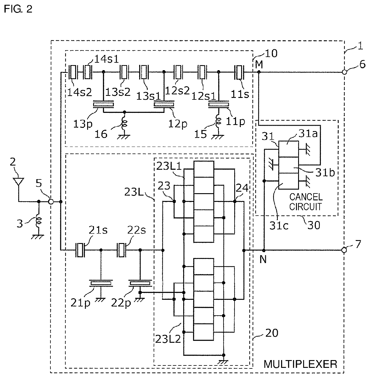
[0039]The multiplexer 1 includes a transmission-side filter 10, a reception-side filter 20, a cancel circuit 30, a common connection terminal 5, a transmission-side terminal 6, and a reception-side terminal 7. The transmission-side filter 10 and the reception-side filter 20 are connected to each other at the common connection terminal 5. With this structure, the multiplexer 1 defines and functions as a duplexer. In the duplexer, a high-frequency signal that the antenna element 2 receives is output from the reception-side terminal 7 via the common connection terminal 5 and the reception-side filter 20, and a high-frequency signal that is input from the transmission-side terminal 6 is output to t...

second preferred embodiment

[0108]A multiplexer 100 according to a second preferred embodiment of the present invention will now be described. FIG. 8 is a circuit diagram of the multiplexer 100 according to the present preferred embodiment.

[0109]The multiplexer 100 according to the present preferred embodiment differs from the multiplexer 1 according to the first preferred embodiment in that the cancel circuit includes the longitudinally-coupled resonator and a capacitance element. The other structure is the same or substantially the same as in the first example.

[0110]The multiplexer 100 in a second example will be described as an example of a circuit structure of the multiplexer 100 according to the present preferred embodiment.

[0111]As illustrated in FIG. 8, the multiplexer 100 includes the transmission-side filter 10, the reception-side filter 20, and a cancel circuit 130. The structure of the transmission-side filter 10 and the reception-side filter 20 is the same or substantially the same as the structure...


PUM


Abstract

A multiplexer includes a transmission-side filter, a reception-side filter, and a cancel circuit connected between a node M and a node N to cancel out a component in a predetermined frequency band that flows along first and second paths. The cancel circuit includes at least one longitudinally-coupled resonator. An average pitch between electrode fingers of interdigital transducer electrodes of the at least one longitudinally-coupled resonator is narrower than an average pitch between electrode fingers of interdigital transducer electrodes of each of series arm resonators and parallel arm resonators that determine the pass band of the transmission-side filter and an average pitch between electrode fingers of interdigital transducer electrodes of each of series arm resonators and parallel arm resonators that determine the pass band of the reception-side filter.

Description

CROSS REFERENCE TO RELATED APPLICATIONS[0001]This application claims the benefit of priority to Japanese Patent Application No. 2017-157234 filed on Aug. 16, 2017. The entire contents of this application are hereby incorporated herein by reference.BACKGROUND OF THE INVENTION1. Field of the Invention[0002]The present invention relates to a multiplexer that includes an elastic wave filter.2. Description of the Related Art[0003]In recent years, there has been a need for a cellular phone that supports frequency bands and wireless systems, that is, a multi-band and a multi-mode. To fulfill the need, a multiplexer that separates high-frequency signals having wireless carrier frequencies is disposed next to an antenna.[0004]A duplexer that includes a cancel circuit is disclosed as a multiplexer in Japanese Unexamined Patent Application Publication No. 2013-118611. The cancel circuit includes a longitudinally-coupled elastic wave resonator and electrostatic capacities that are connected bet...

Claims


Application Information

Patent Timeline
Patent Type & Authority Patents(United States)
IPC IPC(8): H03H9/72H03H9/64H03H9/02H03H9/145H04B1/00H03H9/44
CPCH04B1/0057H03H9/6483H03H9/44H03H9/6476H03H9/02818H03H9/6436H03H9/725H03H9/14544H03H9/6489H03H7/38H03H9/25H03H9/17H03H9/6406
Inventor TAKATA, TOSHIAKI
Owner MURATA MFG CO LTD
Why Eureka
Try Eureka