
Electromagnetic-coupling dual IC card and IC module

a dual-core, ic card technology, applied in the direction of near-field systems using receivers, instruments, printing, etc., can solve the problems of difficult to achieve impedance matching, limited location of coupling coils in the card body, and affect communication properties, so as to reduce or prevent the degradation of communication properties, good impedance matching in conformity, and low cost

Active Publication Date: 2021-12-14
TOPPAN PRINTING CO LTD
View PDF14 Cites 0 Cited by
  • Summary
  • Abstract
  • Description
  • Claims
  • Application Information

AI Technical Summary

Benefits of technology

This configuration reduces communication degradation, enhances impedance matching, and allows for the production of a more durable and cost-effective dual IC card with improved design flexibility and communication performance.

Problems solved by technology

The IC modules of the electromagnetic-coupling dual IC cards as mentioned above may impair communication properties due to reaction magnetic flux or the like caused by eddy current which is generated by interaction of the connecting coil with the contact terminals.
However, the location of the coupling coil in the card body is limited because the location of the IC module relative to the card body is prescribed by a standard (JIS X6320-2: 2009 (ISO / IEC 7816: 2007)) or the card body needs to be provided with an embossing area (e.g., JIS X6302-1: 2005 (ISO / IEC 7811-1: 2002)) enabling embossing.
Therefore, it is not always easy to achieve impedance matching by adjusting the location of the coupling coil.
However, the electromagnetic-coupling dual IC cards as mentioned above have an area limitation in the surface where the IC chip is mounted.
Therefore, it is not always easy to adjust the number of turns or the location of the connecting coil.

Method used


Image

  • Electromagnetic-coupling dual IC card and IC module
  • Electromagnetic-coupling dual IC card and IC module
  • Electromagnetic-coupling dual IC card and IC module

Examples


Embodiment Construction

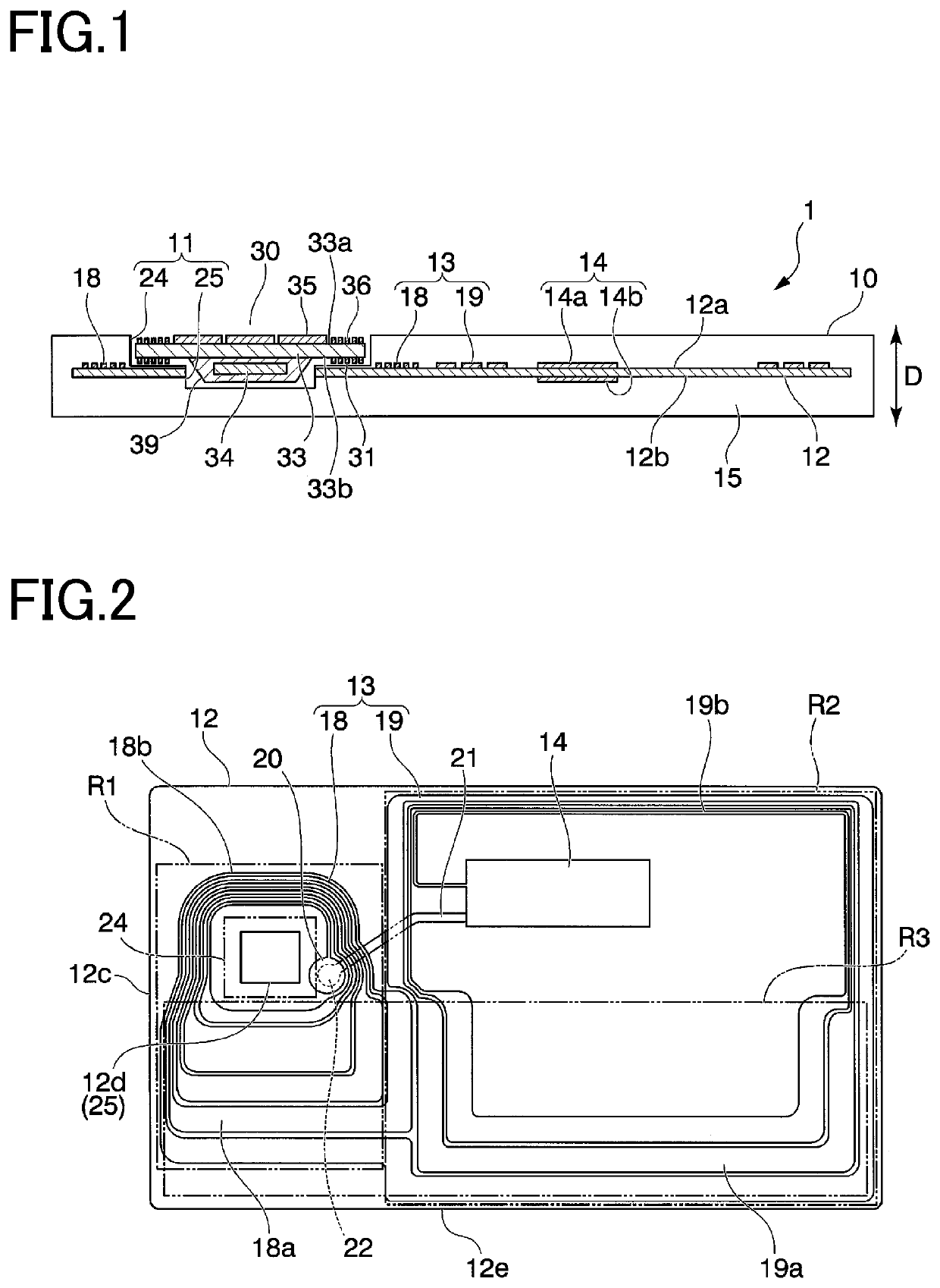
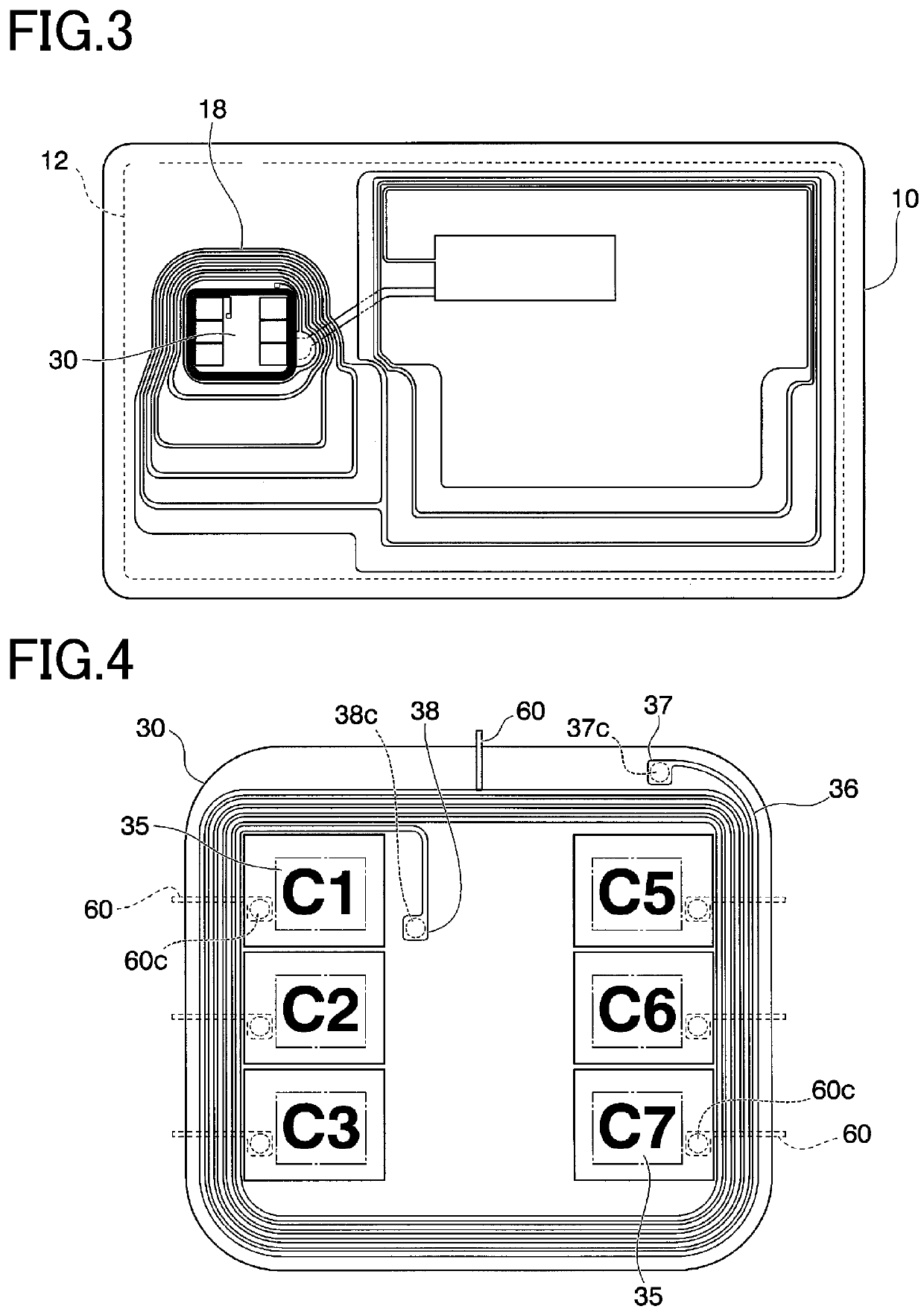
[0039]With reference to FIGS. 1 to 4, an electromagnetic-coupling dual IC card according to an embodiment of the present invention will be described. The preferred embodiments of the present invention will now be described in detail with reference to the drawings. The present invention is not limited to the following representative embodiments, and appropriate modifications can be made without departing from the spirit of the present invention. The representative embodiments described below are merely examples of the present invention, and the design thereof could be appropriately changed by one skilled in the art. The same constituent elements are denoted by the same reference numerals unless there is a reason for the sake of convenience, and redundant description is omitted. In the drawings referred to in the following description, for clarity, characteristic parts are enlarged, and thus the components are not shown to scale.

[0040]FIGS. 1 and 2 show an electromagnetic-coupling dua...


PUM


Abstract

An electromagnetic-coupling dual IC card includes an IC module and a plate-like card body. The IC module includes a module substrate having a first surface and a second surface, contact terminals provided on the first surface of the module substrate to be contactable with an external contact-type device, an IC chip having a contact communication function and a contactless communication function and disposed on the second surface, and a first connecting coil provided on the first surface. The plate-like card body includes an antenna sheet embedded therein and has a recess for holding the IC module, the antenna sheet being provided with a coupling coil to be electromagnetically coupled to the first connecting coil, and a main coil connected to the coupling coil to perform contactless communication with an external contactless-type device. The first connecting coil does not overlap with the contact terminals in plan view.

Description

CROSS-REFERENCE TO RELATED PATENT APPLICATIONS[0001]This application is a Bypass Continuation of International Patent Application No. PCT / JP2017 / 041550, filed on Nov. 17, 2017, which is based upon and claims the benefit of priority of Japanese Patent Application No. 2016-224863, filed on Nov. 18, 2016, the entire contents of all of these are hereby incorporated by reference in their entireties.TECHNICAL FIELD[0002]The present invention relates to a dual IC card having both a contact communication function and a contactless communication function, and an IC module, and in particular, relates to an electromagnetic-coupling dual IC card in which an antenna sheet having an antenna coil for performing contactless communication can be electromagnetically coupled, via a coupling coil, to an IC module for performing both of the communication functions, and an IC module used for the electromagnetic-coupling dual IC card.BACKGROUND ART[0003]Dual IC cards having a contact communication functio...

Claims


Application Information

Patent Timeline
Patent Type & Authority Patents(United States)
IPC IPC(8): G06K19/06G06K19/077B42D25/305H04B5/02H01Q7/00H04B5/48
CPCG06K19/07783B42D25/305G06K19/077G06K19/0775G06K19/07747H04B5/02H01Q7/00G06K19/07794H04B5/26H04B5/43H04B5/48
Inventor UEHARA, ERIKOTSUKADA, TETSUYA
Owner TOPPAN PRINTING CO LTD
Learn More