Brake system providing limited antiskid control during a backup mode of operation

a brake system and backup mode technology, applied in the direction of braking systems, automatic braking sequences, aircraft braking arrangements, etc., can solve the problems of limited hydraulic brake fluid storage in the accumulator, accumulator being emptied relatively quickly, and the functions of the brake system may not be available, so as to reduce the braking efficiency of the brake system

Active Publication Date: 2020-12-31
THE BOEING CO
View PDF0 Cites 8 Cited by
  • Summary
  • Abstract
  • Description
  • Claims
  • Application Information

AI Technical Summary

Benefits of technology

[0006]According to another aspect, an aircraft is disclosed. The aircraft includes a brake system including a plurality of wheels and an accumulator, where the accumulator is configured to store and discharge fluid energy as a pressurized hydraulic brake fluid. The aircraft also includes one or more processors operatively coupled to the accumulator and in electrical communication with the plurality of wheels and a memory coupled to the one or more processors. The memory stores data comprising a database and program code that, when executed by the one or more processors, causes the brake system to determine the brake system is operating in a backup mode of operation, where the backup mode of operation co

Problems solved by technology

However, the accumulator is only able to store a limited amount of hydraulic brake fluid.
In an effort to preserve the hydraulic fluid stored within the accumulator, some functions of the brake system may not be available when the accumulator is being used as a backup source of fluid energy.
Omitting antiskid control may create issues if the aircraft is traveling along a slippery surface, such as an icy runway.
However, this may result in the accumulator being emptied relatively quickly if the brakes are released excessively because of skid protection.
The brake system is also caused to determine a slip error by comparing the dynamic slip with a target slip value of the plurality of wheels, where the target slip value is offset from an ideal slip value of the plurality of wheels and results in a reduced braking efficiency of the brake system.
The brake system is also caused to calc

Method used


Image

  • Brake system providing limited antiskid control during a backup mode of operation
  • Brake system providing limited antiskid control during a backup mode of operation
  • Brake system providing limited antiskid control during a backup mode of operation

Examples


Embodiment Construction

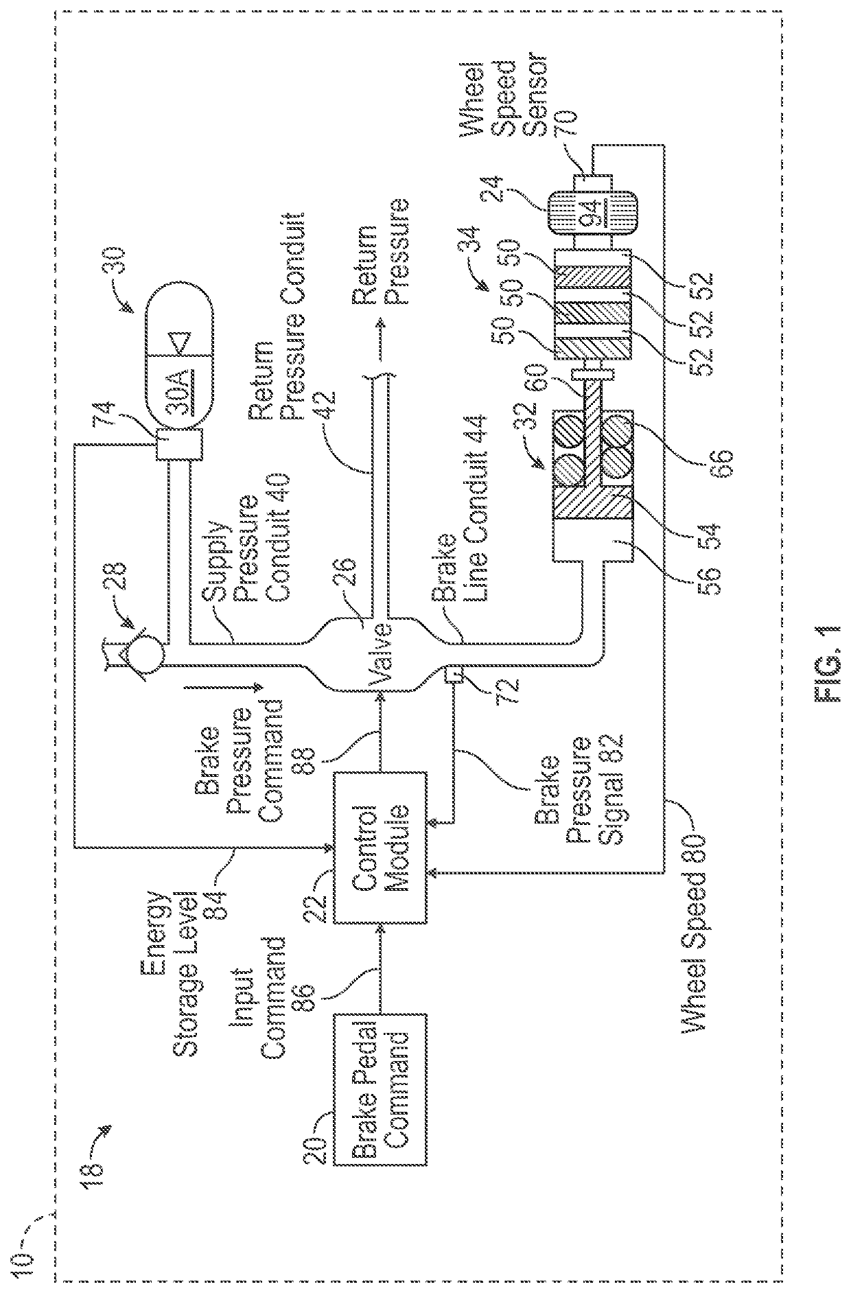
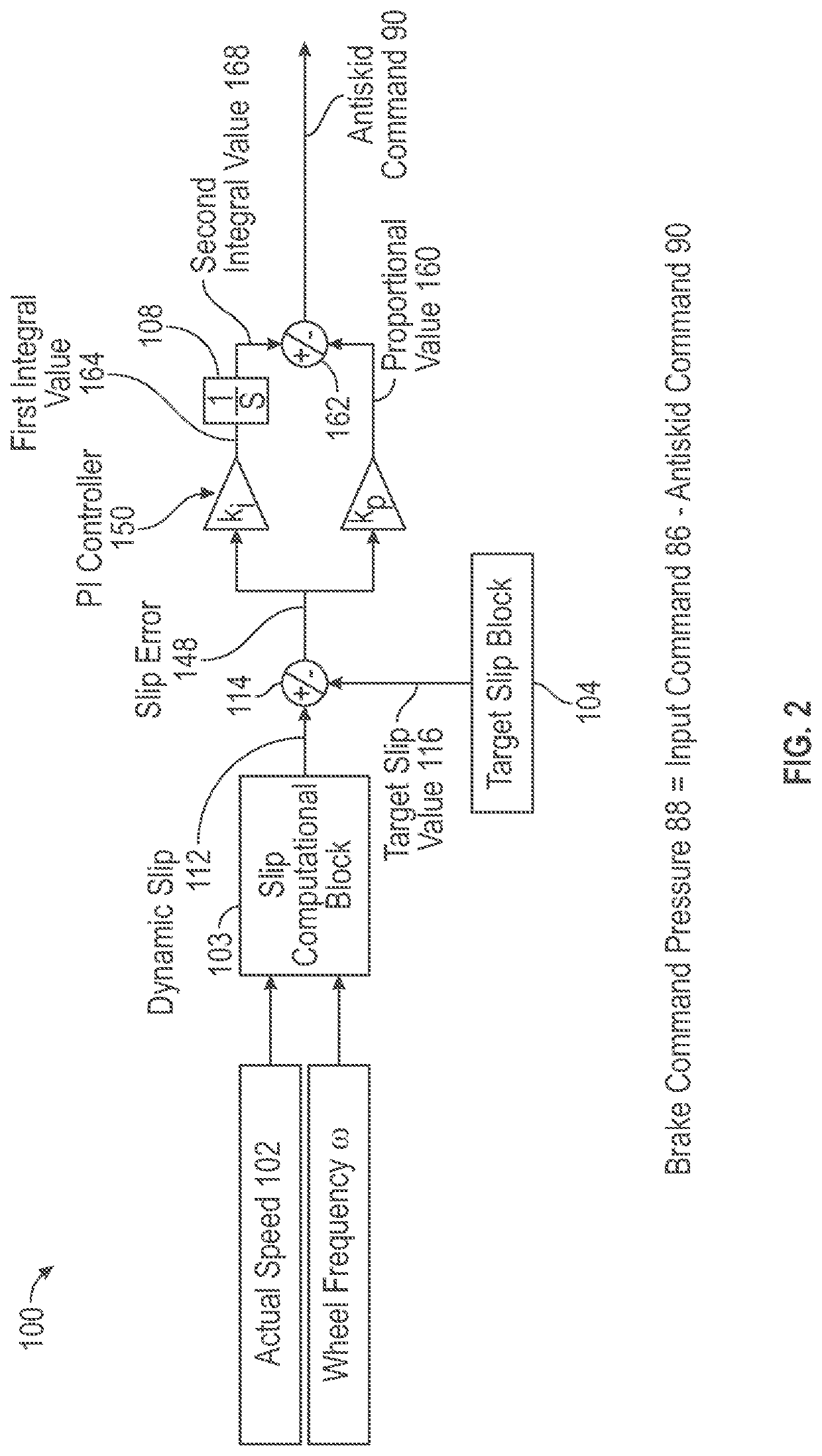
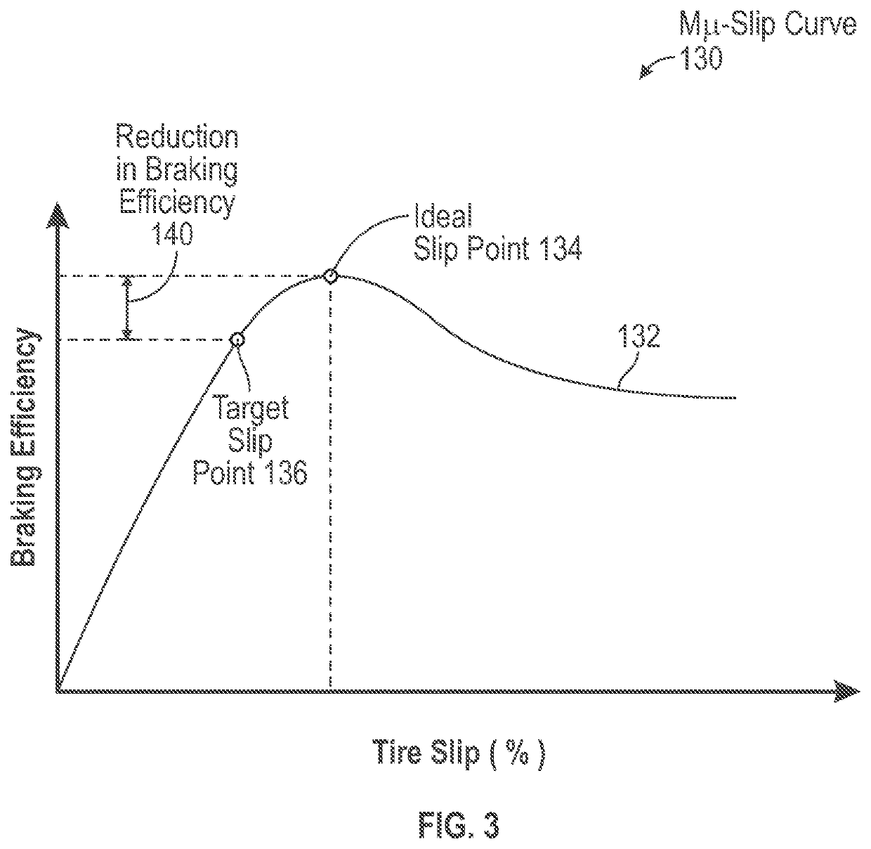
[0021]The disclosure is directed towards a brake system for a vehicle, where the brake system includes an energy storage device. During a backup mode of operation, the energy storage device is used to supply energy to the brake system. The brake system conserves an amount of energy that is stored within the energy storage device during the backup mode of operation. Specifically, a control module of the brake system determines an antiskid command that represents a reduction in brake pressure applied to the wheels of the vehicle. The antiskid command is calculated based on an error between a dynamic slip of the wheels and a target slip value of the wheels. The target slip value is offset from an ideal slip value of the wheels, and results in a reduced stopping efficiency of the brake system. However, since the target slip results in a reduced amount of brake pressure applied to the wheels, the brake system consumes less energy from the energy storage device each time brakes are applie...


PUM


Abstract

A brake system for a vehicle is disclosed and includes an energy storage device configured to store and discharge energy, a plurality of wheels, one or more processors operatively coupled to the energy storage device, and a memory coupled to the one or more processors. The memory stores data comprising a database and program code that, when executed by the one or more processors, causes the brake system to determine the brake system is operating in a backup mode of operation. In response to determining the brake system is operating in the backup mode of operation, the brake system calculates a dynamic slip of the plurality of wheels. The brake system is caused to determine a slip error by comparing the dynamic slip with a target slip value of the plurality of wheels. The brake system is also caused to calculate an antiskid command based on the slip error.

Description

INTRODUCTION[0001]The present disclosure relates to a brake system for a vehicle. More particularly, the present disclosure is directed towards a brake system that employs a limited antiskid control strategy during a backup mode of operation to conserve energy stored within an energy storage device.BACKGROUND[0002]Aircraft brakes are used in a variety of situations. For example, aircraft brakes are used to slow the aircraft down during landing roll along a runway. Aircraft brakes may also be used during ground handling operations such as, for example, taxiing, steering, and parking.[0003]Hydraulic aircraft brake systems include an accumulator that stores hydraulic braking fluid under pressure. The accumulator is used as a redundant pressure source as well as a backup source of fluid energy. Specifically, the braking accumulator is primarily used to provide sustained hydraulic pressure after the active hydraulic system is depressurized, and is also used as a backup source of energy i...

Claims


Application Information

Patent Timeline
IPC IPC(8): B64C25/42B60T8/17B60T8/176B60T8/172
CPCB60T2270/402B60T2270/10B64C25/426B60T8/176B60T8/1703B60T8/172B64C25/46B60T13/66B60T8/325B60T2270/414
Inventor FORGHANI, NIMAYAMAMOTO, DAVID T.SMITH, STEVEN ELLIOT
Owner THE BOEING CO
Why Eureka
Try Eureka