Division line recognition apparatus

Active Publication Date: 2020-12-31
FAURECIA CLARION ELECTRONICS CO LTD
View PDF0 Cites 2 Cited by
  • Summary
  • Abstract
  • Description
  • Claims
  • Application Information

AI Technical Summary

Benefits of technology

This patent improves the ability to recognize division lines on a road.

Problems solved by technology

So, there has been a problem of difficulty in determining which feature points indicate the boundary of the division line.
Furthermore, when the luminance value of the division line decreases due to the influence of, for example, shadows of vehicles or the luminance value of a road surface rises due to a reflection of strong light on the road surface, there has also been a problem of difficulty in distinguishing between the division line and the road surface.

Method used


Image

  • Division line recognition apparatus
  • Division line recognition apparatus
  • Division line recognition apparatus

Examples


first embodiment

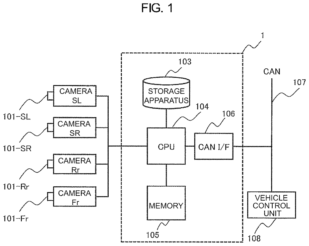
[0026]FIG. 1 is a diagram illustrating an example of a hardware configuration of a division line recognition apparatus according to one embodiment of the present invention. A division line recognition apparatus 1 illustrated in FIG. 1: is designed to recognize division lines on a road from an image(s) captured by a camera as it is mounted in a vehicle and used; and includes a storage apparatus 103, a CPU 104, a memory 105, and a CAN I / F 106. The following cameras are coupled to the division line recognition apparatus 1: a front camera 101-Fr for monitoring an area in front of the vehicle; a rear camera 101-Rr for monitoring an area behind the vehicle; a left-side camera 101-SL for monitoring an area on the left side of the vehicle; a right-side camera 101-SR for monitoring an area on the right side of the vehicle. Furthermore, a vehicle control unit 108 is coupled to the division line recognition apparatus 1 via a CAN bus 107. Incidentally, in an example in FIG. 1, the above-describ...

second embodiment

[0090]Next, a second embodiment of the present invention will be explained. In this embodiment, an explanation will be provided about an example in which a division line on the road is recognized by using a plurality of images captured in chronological order. Incidentally, the hardware configuration and functional configuration of a division line recognition apparatus according to this embodiment are respectively the same as those explained in the first embodiment, so that an explanation about them has been omitted in the following explanation.

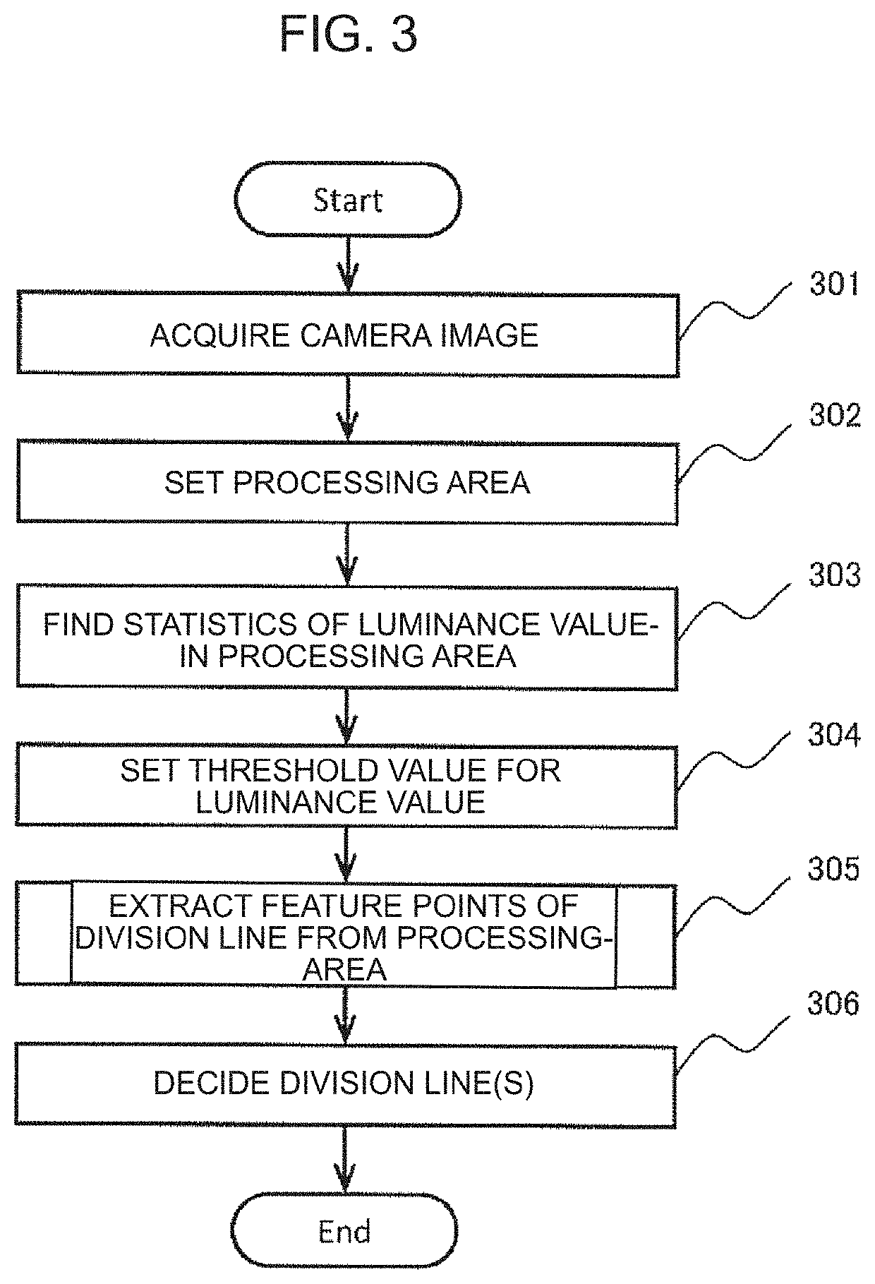
[0091]FIG. 15 is a diagram illustrating a processing flow of a division line recognition apparatus according to a second embodiment of the present invention. With the division line recognition apparatus 1 according to this embodiment, the CPU 104 executes a processing flow illustrated in FIG. 15 following the processing in step 305 in FIG. 3. In this processing flow, pixels which are classified, respectively, as any one of the “road surface,” ...


PUM


Abstract

An apparatus for recognizing a division line on a road from an image captured by a camera includes: a processing area setting unit to set a processing area to the image; a statistics calculation unit to calculate statistics of the image in the processing area; a threshold value setting unit to set a plurality of threshold values on the basis of the statistics; a division line feature point extraction unit to classify a plurality of pixels contained in the image on the basis of the white line threshold value and the road surface threshold value and extracts feature points of the division line on the basis of classification results of the plurality of pixels; and a division line decision unit configured to decide the division line on the basis of the feature points extracted by the division line feature point extraction unit.

Description

CROSS-REFERENCE TO RELATED APPLICATION(S)[0001]This application is a U.S. National Phase Patent Application and claims priority to and the benefit of International Application Number PCT / JP2019 / 007736, filed on Feb. 28, 2019, which claims priority of Japanese Patent Application Number 2018-043554, filed on Mar. 9, 2018, the entire contents of all of which are incorporated herein by reference.TECHNICAL FIELD[0002]The present invention relates to an apparatus for recognizing division lines on roads.BACKGROUND ART[0003]Conventionally, there has been known a technology that recognizes division lines (white lines) on a road from a captured image(s) of the road and utilizes them for, for example, controlling vehicles. When a division line is recognized by directly using a luminance value of the captured image, feature points of edges sometimes appear not only at boundary portions of the division line, but also within the division line. So, there has been a problem of difficulty in determi...

Claims


Application Information

Patent Timeline
IPC IPC(8): G06K9/00G06K9/46G06K9/62
CPCG06K9/6268G06K9/4642G06K9/4604G06K9/00798G06T7/136G06T7/13G06T2207/30256G08G1/09623H04N7/181G06V20/588H04N23/71H04N23/90G06F18/241
Inventor MACHII, KIMIYOSHIOGATA, TAKEHITOSHIMIZUMIYASHITA, AYANO
Owner FAURECIA CLARION ELECTRONICS CO LTD
Why Eureka
Try Eureka