
Systems and Methods for Implementing an Interactive Virtual Design Tool

a virtual design and tool technology, applied in the field of virtual design tools for designing and commercial interior spaces, can solve the problems of unsatisfactory known systems for selecting and installing such options, not providing a way for the designer or homeowner to visualize, in real time, and traditionally difficult task of designing, selecting and installing electrical and lighting features in a new home. the effect of efficient specification of electrical and reducing construction cycle-time and field errors

Pending Publication Date: 2020-12-31
SALMONSON PAUL R
View PDF1 Cites 4 Cited by
  • Summary
  • Abstract
  • Description
  • Claims
  • Application Information

AI Technical Summary

Benefits of technology

The present invention is a virtual, interactive floorplan system that is integrated into a supply chain. This system allows designers, homeowners, builders, and installers to efficiently specify electrical, lighting, and other home technology items in a way that reduces construction cycle-time and field errors. The system provides web-based portals and user interfaces that are branded within the home builders' website and options-selection systems. The interactive floorplan system allows the homeowner to visualize the home not only in a top-down 2D mode, but also in a 3D virtual, interactive mode in which the homeowner can dynamically visualize the aesthetic and illumination effects of a variety of different lighting options. The tool also generates purchase orders and trade-specific installation instructions in the form of lot-specific plans, orders, and bills of materials for use by the builder and the installing trades.

Problems solved by technology

The task of designing, selecting, and installing electrical and lighting features within a new home has traditionally been a difficult task, involving a number of different parties—e.g., home buyers, designers, home builders, and tradesmen.
Currently known systems for selecting and installing such options are unsatisfactory in a number of respects.
For example, prior art interactive floorplan systems generally allow only limited 3D visualization of the interior, and do not provide a way for the designer or homeowner to visualize, in real time, the visual effect of a particular option selection.
Furthermore, such systems are not linked to a kit / parts supply chain in a manner that allows both retail and wholesale pricing, P.O.'s, and bills-of-material to be generated quickly and in a way that is responsive to changes made by the parties.
As a result, such systems are prone to errors, leading to increased costs and construction cycle-times.

Method used


Image

  • Systems and Methods for Implementing an Interactive Virtual Design Tool
  • Systems and Methods for Implementing an Interactive Virtual Design Tool
  • Systems and Methods for Implementing an Interactive Virtual Design Tool

Examples


Embodiment Construction

[0017]The following detailed description of the invention is merely exemplary in nature and is not intended to limit the invention or the application and uses of the invention. Furthermore, there is no intention to be bound by any theory presented in the preceding background or the following detailed description.

[0018]Various embodiments of the present invention relate to an improved, web-based interactive design tool for lighting, electrical, and other home technology options.

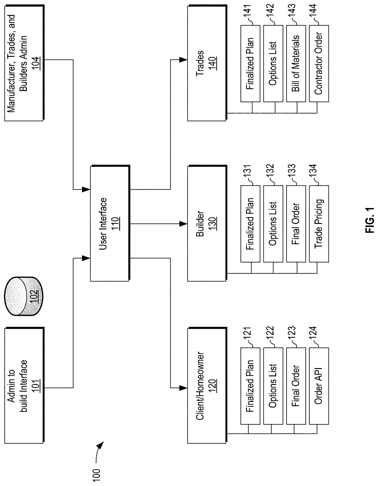
[0019]Referring now to the general block diagram of FIG. 1, a virtual interactive design tool system (“design tool,” or simply “system”) 100 in accordance with various embodiments generally includes an admin interface 101, a datastore and / or database system 102, and a manufacturer, trades, and builders admin interface (“builders admin interface”) 104, all of which may be employed to provide a web-based user interface 110. As shown, user interface 110 can be accessed by multiple parties, and provides appropriat...


PUM


Abstract

A virtual, interactive floorplan system includes a database system configured to store data associated with a plurality of home interior options, and a web-based portal communicatively coupled to the database system, wherein the web-based portal is configured to provide a user interface. The user interface provides: (a) an option-selection mechanism through which a user can select, for a specified home design, one or more options from the plurality of home interior options; (b) a graphical visualization of the specified home design from a 2D plan view and a 3D virtual interactive mode that together display the effect of selecting the home interior options; (c) a report generation mechanism through which the user can generate purchase orders and trade specific installation instructions in the form of at least lot-specific plans, orders, and a bill of materials.

Description

CROSS-REFERENCE TO RELATED APPLICATIONS[0001]This application claims priority to U.S. Provisional Patent Application Ser. No. 62 / 867,722, filed Jun. 27, 2019, the entire contents of which are hereby incorporated by reference.TECHNICAL FIELD[0002]The present invention generally relates to the design of residential and commercial interior spaces. In particular, the present invention relates to the visualization, planning, and purchasing of electrical, lighting, and other home technology options.BACKGROUND[0003]The task of designing, selecting, and installing electrical and lighting features within a new home has traditionally been a difficult task, involving a number of different parties—e.g., home buyers, designers, home builders, and tradesmen. Currently known systems for selecting and installing such options are unsatisfactory in a number of respects.[0004]For example, prior art interactive floorplan systems generally allow only limited 3D visualization of the interior, and do not ...

Claims


Application Information

Patent Timeline
Patent Type & Authority Applications(United States)
IPC IPC(8): G06Q30/06G06T19/00
CPCG06T2210/04G06Q30/0643G06Q30/0633G06F3/0482G06T19/00G06F3/04815G06T2200/24G06T19/20
Inventor SALMONSON, PAUL R.
Owner SALMONSON PAUL R
Learn More