Fluorescence detecting device and fluorescence detecting method

a fluorescence detection and fluorescence technology, applied in the direction of luminescent dosimeters, optical radiation measurement, instruments, etc., can solve the problems of inability to analyze biologic materials efficiently in a short time by using a large variety of micro beads at once, difficult to identify and analyze an extremely large number of objects to be measured, etc., to achieve efficient specification of objects, increase the number of identifiable kinds of fluorescence, and be measured in a short time

Inactive Publication Date: 2010-10-26
MITSUI ENG & SHIPBUILD CO LTD
View PDF13 Cites 8 Cited by
  • Summary
  • Abstract
  • Description
  • Claims
  • Application Information

AI Technical Summary

Benefits of technology

[0038]According to the present invention, micro beads etc. are set as objects to be measured, and the objects to be measured are irradiated with a laser beam that has been modulated in intensity at a given frequency to obtain a fluorescence relaxation time of the fluorescence that is generated by the irradiation with the laser beam. Since the fluorescence relaxation time varies depending on the kind of fluorochromes, it is possible to identify the kinds of fluorescence, particularly the kinds of objects to be measured by using the fluorescence relaxation time. In other words, since the fluorescence relaxation time can be used to identify the fluorescence besides the wavelength of fluorescence and the intensity of fluorescence which have been conventionally used to identify the fluorescence, the number of identifiable kinds of fluorescence is increased. In particular, the present invention is effective for a flow cytometer that efficiently specifies the object to be measured in a short time by using a large number of fluorochromes.
[0039]Further, in the case of using plural laser beams, coding sequence signals that are orthogonal to each other in each of the laser beams are used as pulse control signals of the laser beams, thereby making it possible to specify which laser beam causes the received fluorescence signal to be generated by the irradiation. As a result, it is possible to efficiently specify the objects to be measured in a short time.
[0040]Further, according to the present invention, even if the labeled samples that are labeled with the plural fluorochromes are irradiated with the laser beams, it is possible to obtain gain constants corresponding to the fluorescence intensities. In this situation, since the laser beams are modulated in time at a given frequency, it is possible to detect phase difference information from one photoelectric converter. Accordingly, since the fluorescence intensities are obtained by using those values, the number of kinds of identifiable fluorescence from the measurement can be increased as compared with the conventional art when the number of arranged photoelectric converter is fixed.
[0041]Further, since a first calibration and a second calibration for calculating fluorescence relaxation time constants and gain constants by using an unlabeled sample and the respective labeled samples are conducted before the fluorescence intensities of the plural kinds of labeled samples are calculated, it is possible to obtain the fluorescence intensities of the plural kinds of labeled samples with high precision.

Problems solved by technology

For that reason, there arises such a problem that it is difficult to identify and analyze an extremely large number of objects to be measured in a short time even if the above flow cytometer is used.
However, in order to analyze the characteristics of the biologic material in a short time by providing various micro beads having various coupling structures, an extremely large number of kinds of fluorochromes are required.
However, since the number of kinds of fluorescent reagents identifiable at the same time is small, it is impossible to analyze the biologic material efficiently in a short time by using a large variety of micro beads at once.
However, in this case, it is necessary to provide a large number of laser beams and a large number of light receiving sections in correspondence with the number of measurement points.
Further, since a flow tube that forms the flow cell is elongated, the flow path resistance of the sheath solution that flows in the tube becomes large, and a pressure to be exerted on the sheath solution becomes large.
For that reason, there arises such a problem that the device is increased in size.
As a result, the costs of the flow cytometer and the processing devices are increased.
For that reason, there arises such a problem that the kinds of identifiable fluorescence that are measured at the same time are restricted in the number according to the number of arranged photoelectric converters.

Method used


Image

  • Fluorescence detecting device and fluorescence detecting method
  • Fluorescence detecting device and fluorescence detecting method
  • Fluorescence detecting device and fluorescence detecting method

Examples


first embodiment

[0093]First, the present invention will be described.

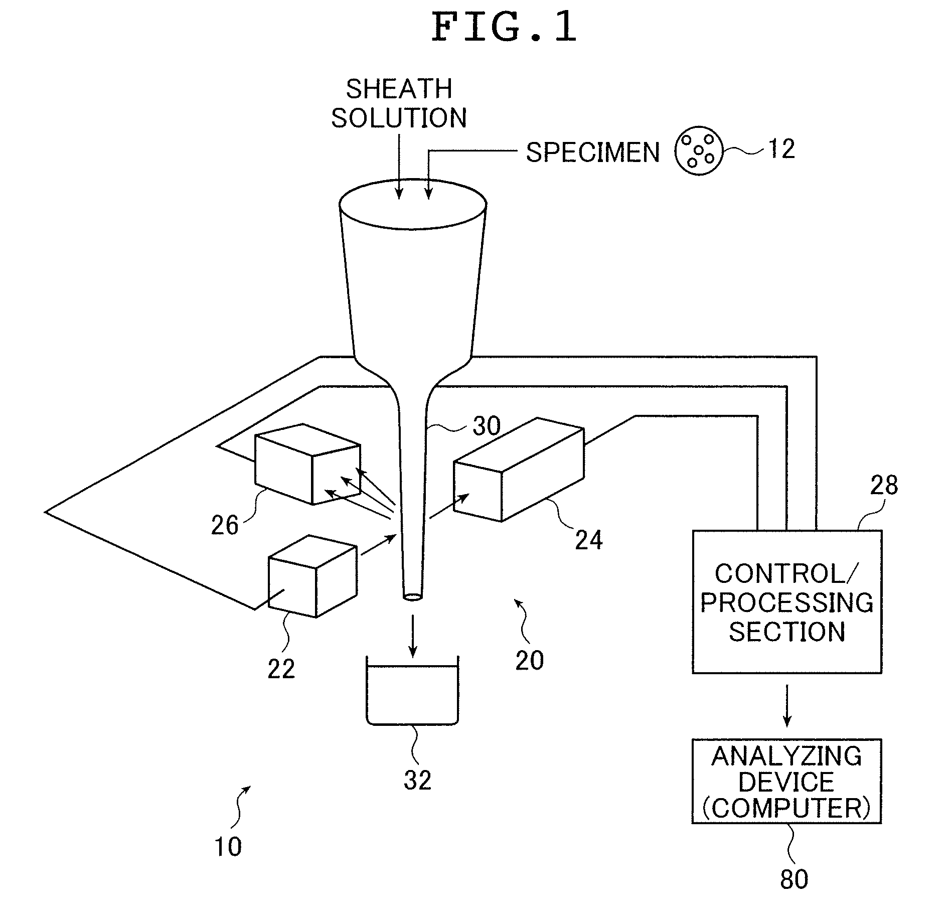
[0094]FIG. 1 is a schematic structural diagram showing a flow cytometer 10 using a fluorescence detecting device using an intensity-modulated laser beam according to the present invention.

[0095]A flow cytometer 10 includes a signal processing device 20 that irradiates a specimen 12 such as micro beads to be measured with a laser beam, and detects a fluorescence signal of fluorescence that is generated by fluorochromes disposed in the specimen 12 to process a signal, and an analyzing device (computer) 80 that analyzes the objects to be measured in the specimen 12 on the basis of the processed results that have been obtained by the signal processing device 20.

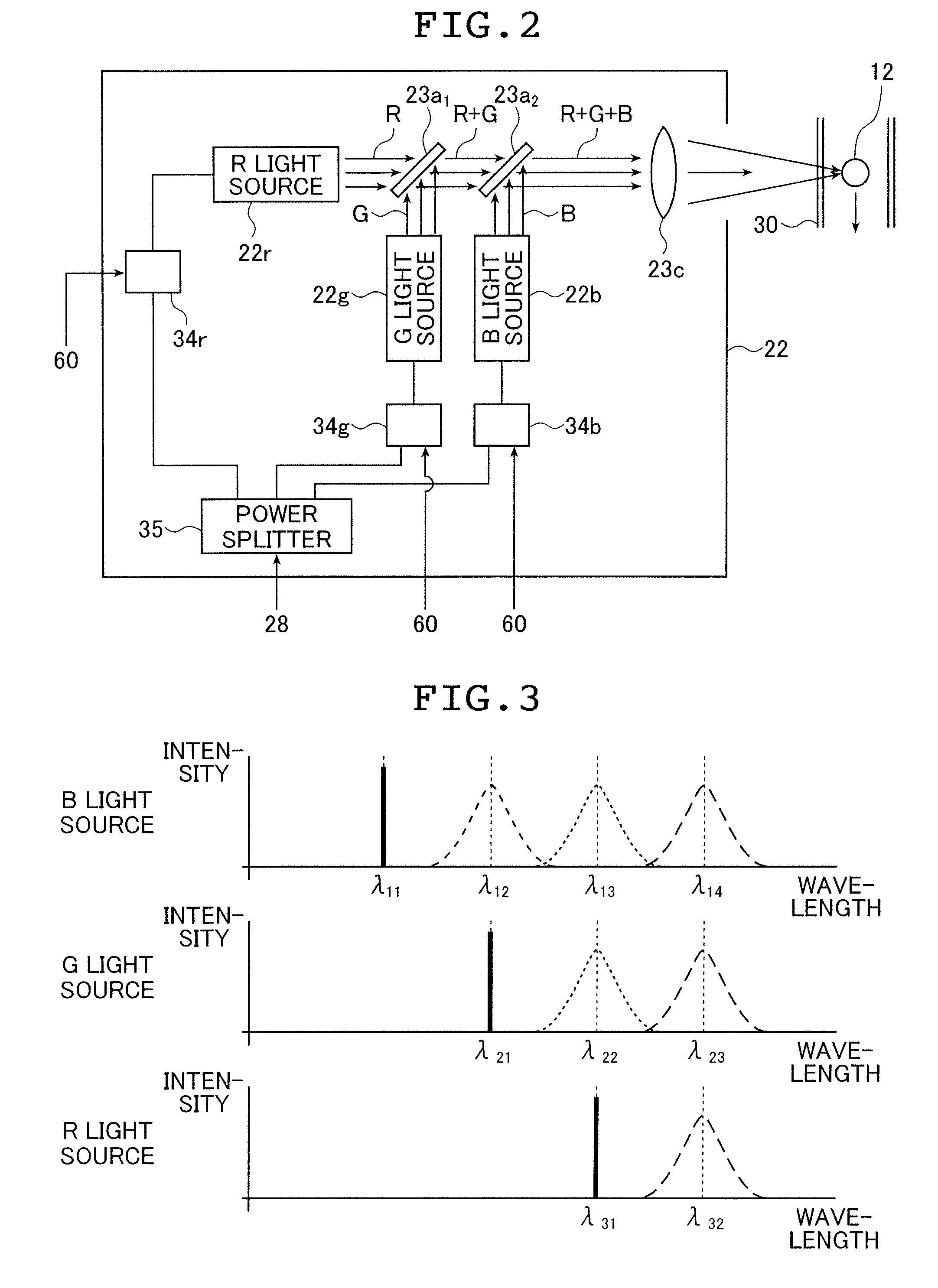
[0096]The signal processing device 20 includes a laser light source section 22, light receiving sections 24 and 26, a control / processing section 28 including a control section that modulates in intensity the laser beam from the laser light source section 22 at a given frequency...

second embodiment

[0172]Subsequently, a fluorescence detecting device according to the present invention will be described below.

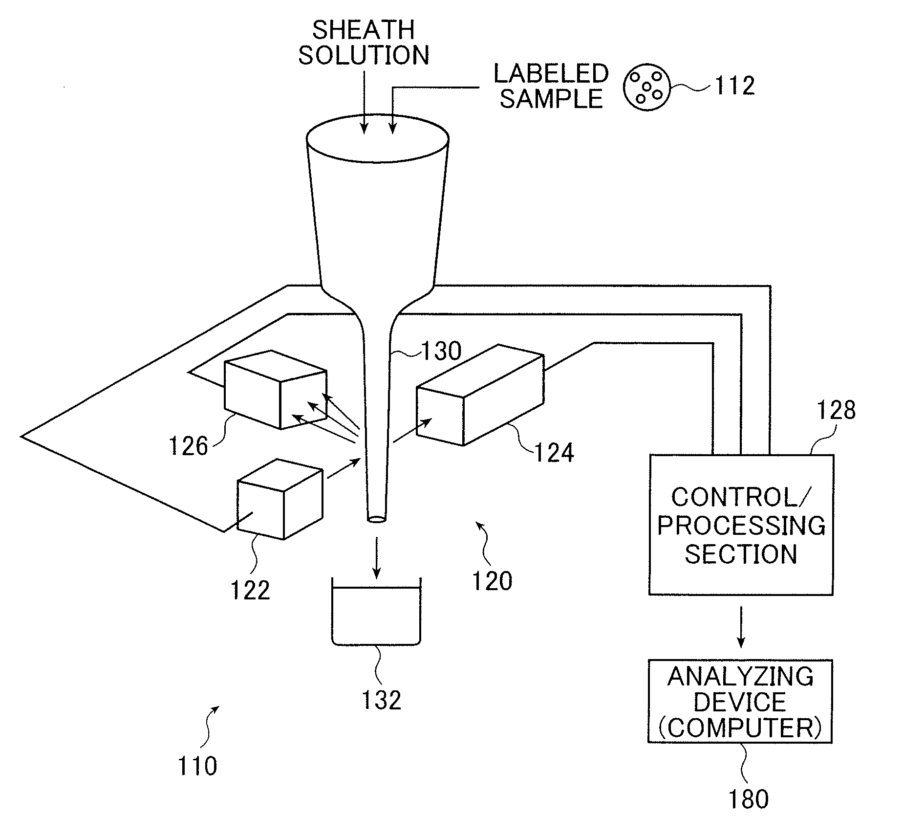
[0173]FIG. 9 is a schematic structural diagram showing a flow cytometer 110 using a fluorescence intensity detecting device with an intensity-modulated laser beam according to the present invention.

[0174]The flow cytometer 110 includes a signal processing device 120 that irradiates, with a laser beam, labeled samples 112 that are labeled by adhering the fluorochromes to receptor samples (hereinafter referred to as “samples”) such as micro beads or specific cells by a chemical coupling or physical coupling, and detects the fluorescence signals of fluorescence that are generated by the labeled samples 112 to process the signals. The flow cytometer 110 also includes an analyzing device (computer) 180 that analyzes the labeled samples 112 according to the processing result which is obtained by the signal processing device 120. The samples themselves conduct autofluorescence acc...


PUM


Abstract

A fluorescence detecting device irradiates an object to be measured with a laser beam, receives fluorescence generated from the object and processes a fluorescence signal generated when receiving the fluorescence. The device includes a laser light source section outputting the laser beam for irradiating the object, a light receiving section outputting the fluorescence signal of the fluorescence generated by the irradiated object, a light source control section generates a modulation signal having a frequency in order to time-modulate an intensity of the laser beam, and a processing section that calculates a fluorescence relaxation time of the fluorescence of the object based on the fluorescence signal output from the light receiving section. From the detection values acquired by the device including the phase information on the fluorescence, the intensity of the fluorescence is calculated.

Description

TECHNICAL FIELD[0001]The present invention relates to a fluorescence detecting device and a fluorescence detecting method, in which an object to be measured is irradiated with a laser beam that has been subjected to intensity modulation, a fluorescence signal from the object to be measured which is attributable to the irradiation is received, and signal processing is conducted on the signal. The fluorescence detecting device and the fluorescence detecting method are applied to, for example, an analyzing device, such as a flow cytometer used in a medical or biological field, which is capable of analyzing the object to be measured in a short period of time by identifying fluorescence that is emitted by a fluorochrome due to irradiation of the laser beam to thereby identify the object to be measured while the object to be measured is flowing in a sheath solution. More particularly, the present invention relates to a fluorescence detecting device and a fluorescence detecting method, in ...

Claims


Application Information

Patent Timeline
Patent Type & Authority Patents(United States)
IPC IPC(8): G06F19/00
CPCG01N21/274G01N21/6408G01N21/6428G01N21/645G01N15/1459G01N2021/6419G01N2021/6421G01N2021/6439G01N2021/6482
Inventor KIMURA, NORIAKIDOI, KYOJIYUMII, TAKAYOSHIYOSHIDA, TAKASHINAKADA, SHIGEYUKIHAYASHI, HIRONORIHOSHISHIMA, KAZUTERU
Owner MITSUI ENG & SHIPBUILD CO LTD
Why Eureka
Try Eureka