
X-ray tomosynthesis apparatus, image processing apparatus, and program

Active Publication Date: 2020-12-31
FUJIFILM HEALTHCARE CORP
View PDF0 Cites 2 Cited by
  • Summary
  • Abstract
  • Description
  • Claims
  • Application Information

AI Technical Summary

Benefits of technology

The invention provides an X-ray tomosynthesis apparatus that can accurately find a small, high absorber region in a subject on a 2D measurement projection data.

Problems solved by technology

For this reason, when there is a high absorber having a large X-ray absorption coefficient such as metal inside the subject, there are problems that an artifact is generated at a boundary thereof and an afterimage is generated on a surface adjacent to a tomographic surface where the high absorber is located and another tomographic surface.
The high absorber artifacts cause clinically poor diagnostic performance.
However, in the tomosynthesis image, a change width of a pixel value in one image is large, and it may be difficult to extract the high absorber region by threshold processing such as binarization processing.
However, there are at least 20 or more pieces of measurement projection data for each projection angle acquired by tomosynthesis shooting, and when an operator sets a start point or a start region for each piece of the measurement projection data, it becomes a burden on the operator.
In this case, even when the region expanding method is performed on the 3D measurement projection data as in Japanese Patent No. 6,317,511, since the high absorber region is not continuous in the z direction, region expansion may not be performed.
For this reason, there occurs a problem that the high absorber region may not be extracted by the technology of Japanese Patent No. 6,317,511.

Method used


Image

  • X-ray tomosynthesis apparatus, image processing apparatus, and program
  • X-ray tomosynthesis apparatus, image processing apparatus, and program
  • X-ray tomosynthesis apparatus, image processing apparatus, and program

Examples


Embodiment Construction

[0027]Hereinafter, an embodiment of the invention will be successively described with reference to the drawings.

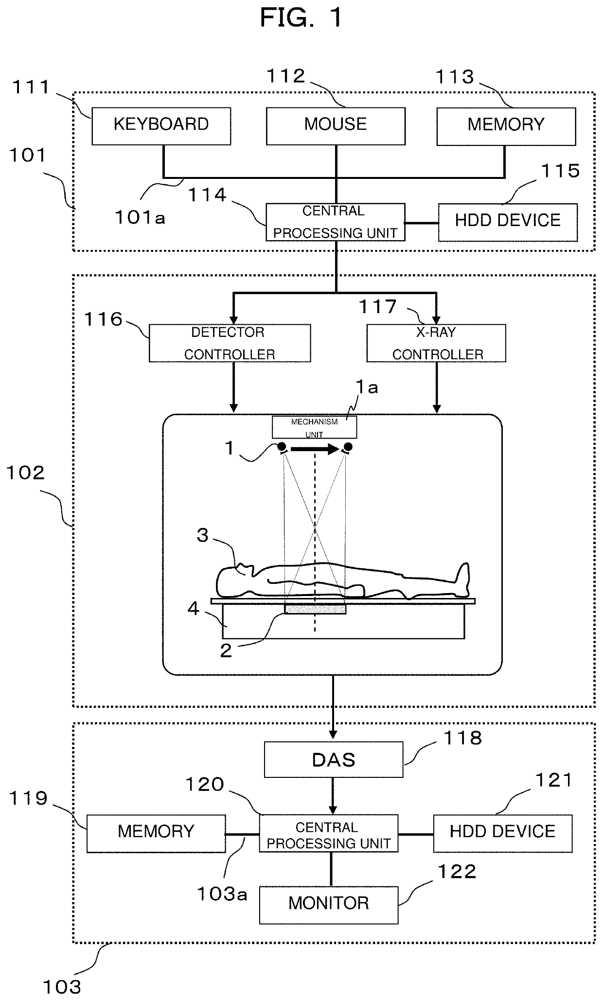
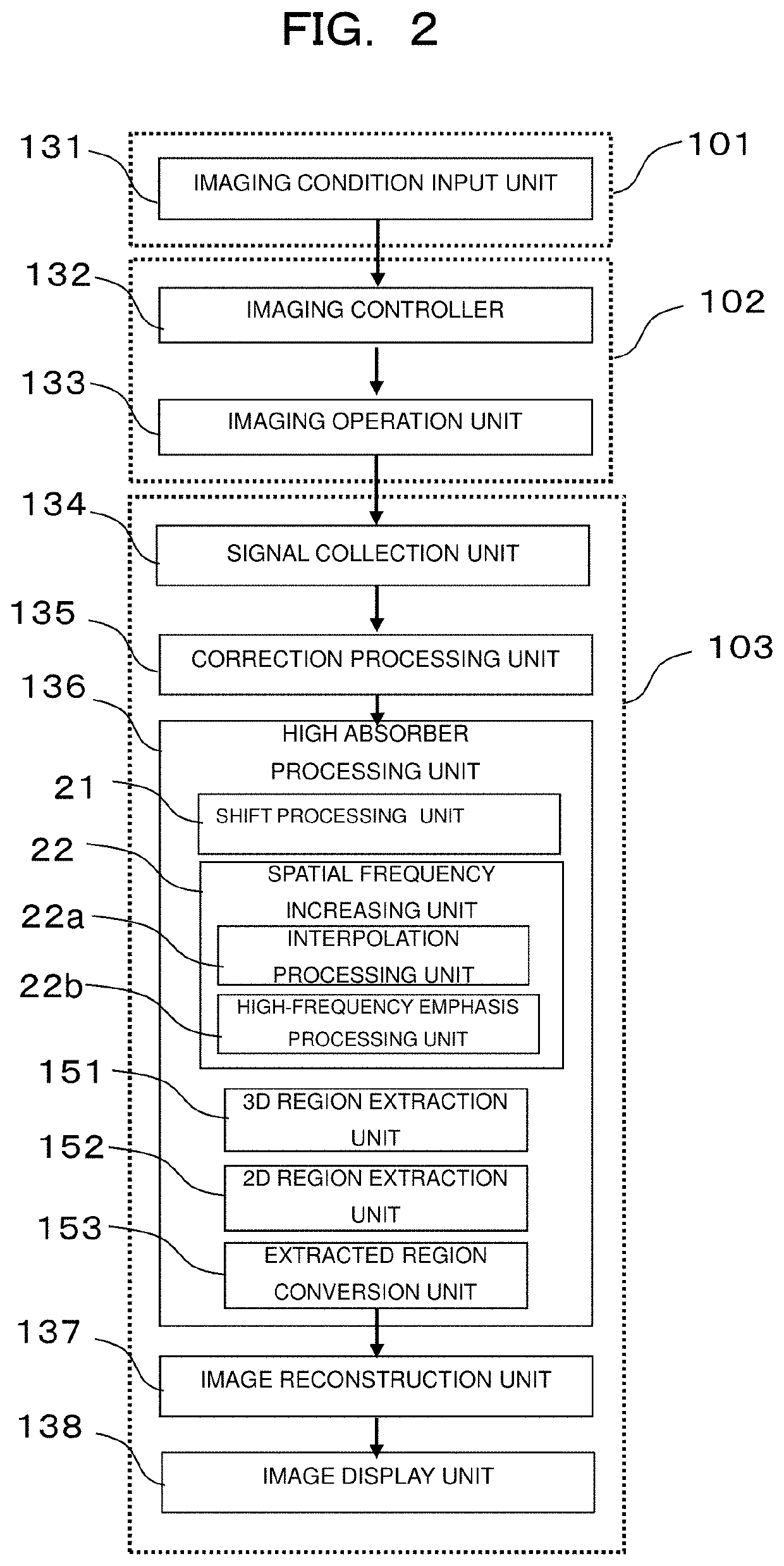
[0028]FIG. 1 illustrates a diagram of a hardware configuration of an X-ray tomosynthesis apparatus according to the embodiment, and FIG. 2 illustrates a functional block diagram illustrating a function of the X-ray tomosynthesis apparatus according to the embodiment. As illustrated in FIG. 2, the present embodiment includes at least an imaging unit 102, a high absorber processing unit 136, and an image reconstruction unit 137. As illustrated in FIG. 1, the imaging unit 102 includes an X-ray generator 1 for irradiating a subject 3 with an X-ray, an X-ray detector 2 that detects an image obtained by projecting an X-ray transmitting through the subject 3 onto a 2D plane and obtains 2D measurement projection data, and a mechanism unit 1a that moves at least one of the X-ray generator and the X-ray detector relative to the subject 3 and irradiates the subject 3 with X-rays from...


PUM


Abstract

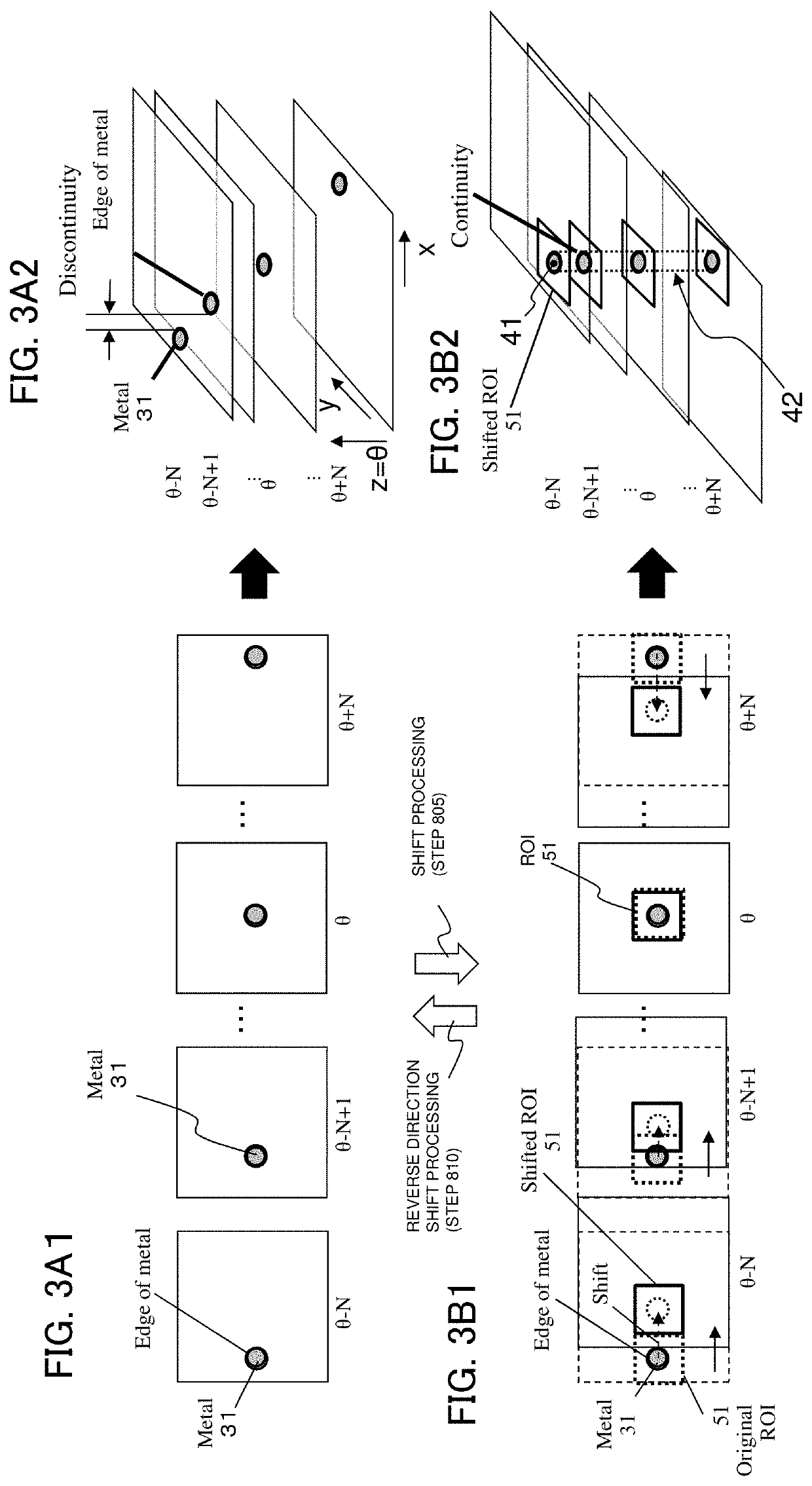
An X-ray tomosynthesis apparatus accurately extracts a region of a small high absorber in a subject on 2D measurement projection data. When pieces of the 2D measurement projection data for each of a plurality of projection angles are arranged in a projection angle direction, the 2D measurement projection data is shifted in a 2D plane so that part or all of a range of a high absorber region included in the 2D measurement projection data overlaps at least a range of the high absorber region included in 2D measurement projection data at an adjacent projection angle in an in-plane direction of the 2D plane. The 2D measurement projection data for each of the plurality of projection angles after shifting is arranged in the projection angle direction to obtain 3D measurement projection data, and a 3D region is obtained from a first start point by a region expansion process.

Description

CROSS-REFERENCE TO RELATED APPLICATION[0001]The present application claims priority from Japanese application JP2019-117683, filed on Jun. 25, 2019, the contents of which is hereby incorporated by reference into this application.BACKGROUND OF THE INVENTION1. Field of the Invention[0002]The present invention relates to an X-ray tomosynthesis apparatus, and more particularly to signal processing and a reconstruction technology for reducing an artifact component generated from a high absorber in a tomosynthesis image.2. Description of the Related Art[0003]Similarly to an X-ray CT apparatus, an X-ray tomosynthesis apparatus is an apparatus that irradiates a subject with X-rays from a plurality of projection angles, calculates an X-ray absorption coefficient of each point in the subject from obtained measurement projection data, and obtain an X-ray absorption coefficient distribution image. Normally, the X-ray absorption coefficient is replaced with a Hounsfield unit value (air is −1000,...

Claims


Application Information

Patent Timeline
IPC IPC(8): G06T11/00G06K9/62G01N23/044
CPCG01N2223/401G06T11/008G06T11/006G01N23/044G06K9/6215A61B6/032A61B6/4411A61B6/54A61B6/467A61B6/5205A61B6/5211G06T2211/436G06V20/647G06V10/25G06V10/44G06V2201/031G06V2201/12G06F18/22
Inventor YAMAKAWA, KEISUKETAKAHASHI, KEIKONAKAMURA, TADASHI
Owner FUJIFILM HEALTHCARE CORP
Learn More