
Magnetic resonance imaging device, phase value correction method and program

Active Publication Date: 2014-10-16
FUJIFILM HEALTHCARE CORP
View PDF1 Cites 5 Cited by
  • Summary
  • Abstract
  • Description
  • Claims
  • Application Information

AI Technical Summary

Benefits of technology

The present invention helps improve the accuracy of correcting distortion in MRI devices caused by eddy currents. It does so by reducing the likelihood of generating additional artifacts during the correction process.

Problems solved by technology

However, even if the method of Non-patent document 2 is used, low frequency components of phase jumps remain, and therefore the ringing artifacts cannot be completely removed.
Moreover, since radio frequency components of eddy currents are cut, sufficient effect of eddy current correction cannot be obtained.
Further, when there are a plurality of sharp phase changes, it is difficult to identify and extract the phase jump regions from them.
Further, when there are a plurality of phase jumps of different phase change amounts, in order to enhance fitting accuracy, it is necessary to perform the fitting for every phase jump generation region, and thus the processing comes to be complicated.
Therefore, it is necessary to determine the phase change amounts of the correction regions in accordance with temporal changes of the phase values, and perform the correction so that the correction regions and the other regions are smoothly connected, and thus the processing comes to be complicated.

Method used


Image

  • Magnetic resonance imaging device, phase value correction method and program
  • Magnetic resonance imaging device, phase value correction method and program
  • Magnetic resonance imaging device, phase value correction method and program

Examples


Embodiment Construction

[0048]Hereafter, embodiments of the present invention will be explained. In all the drawings for explaining the embodiments, components having the same functions are indicated with the same numerals, and repetitive explanations thereof are omitted.

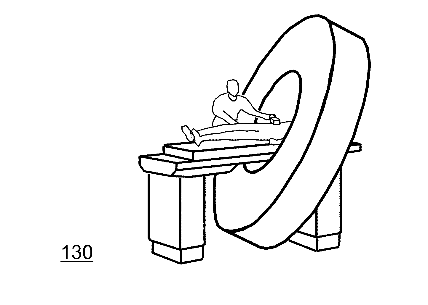
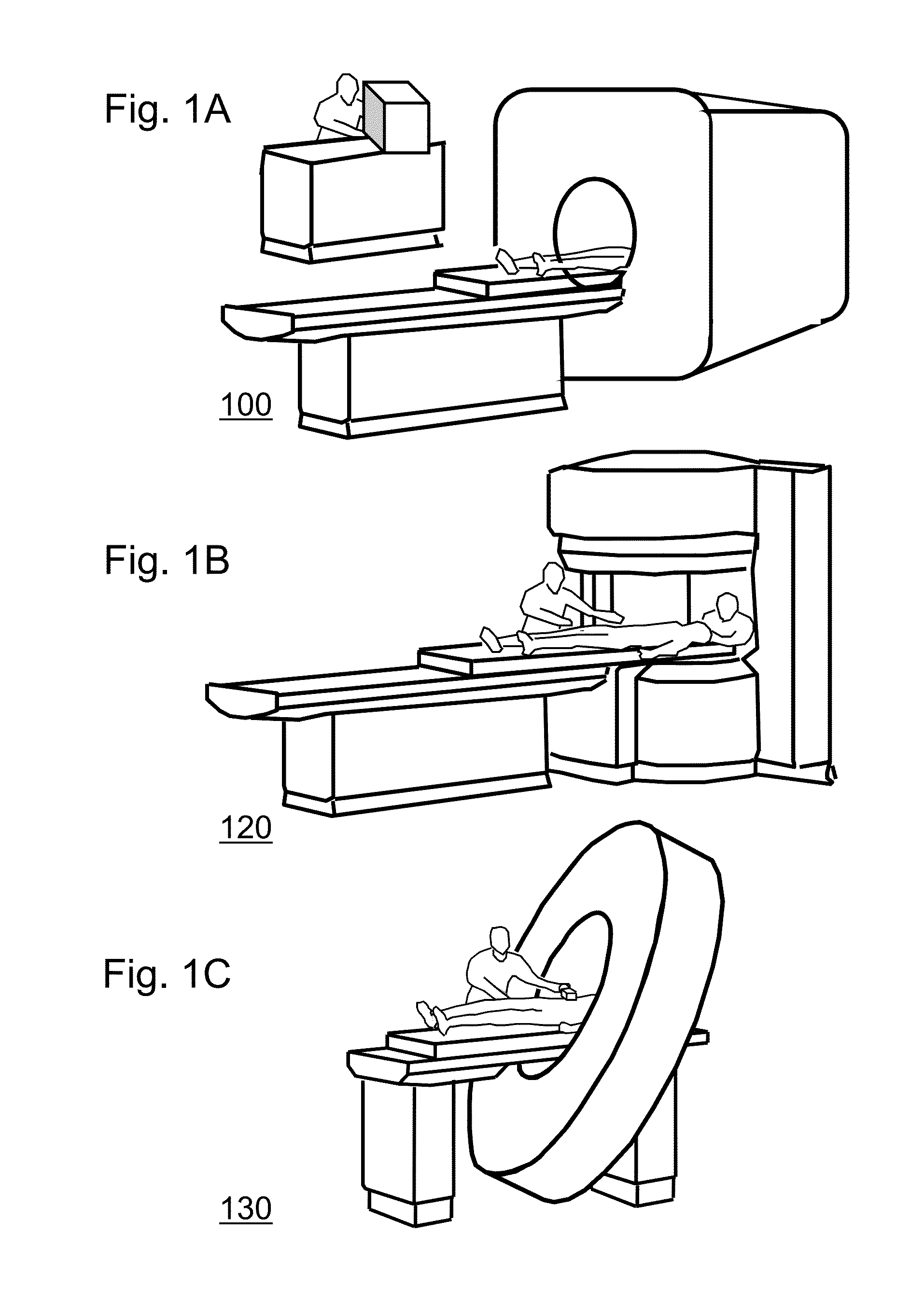
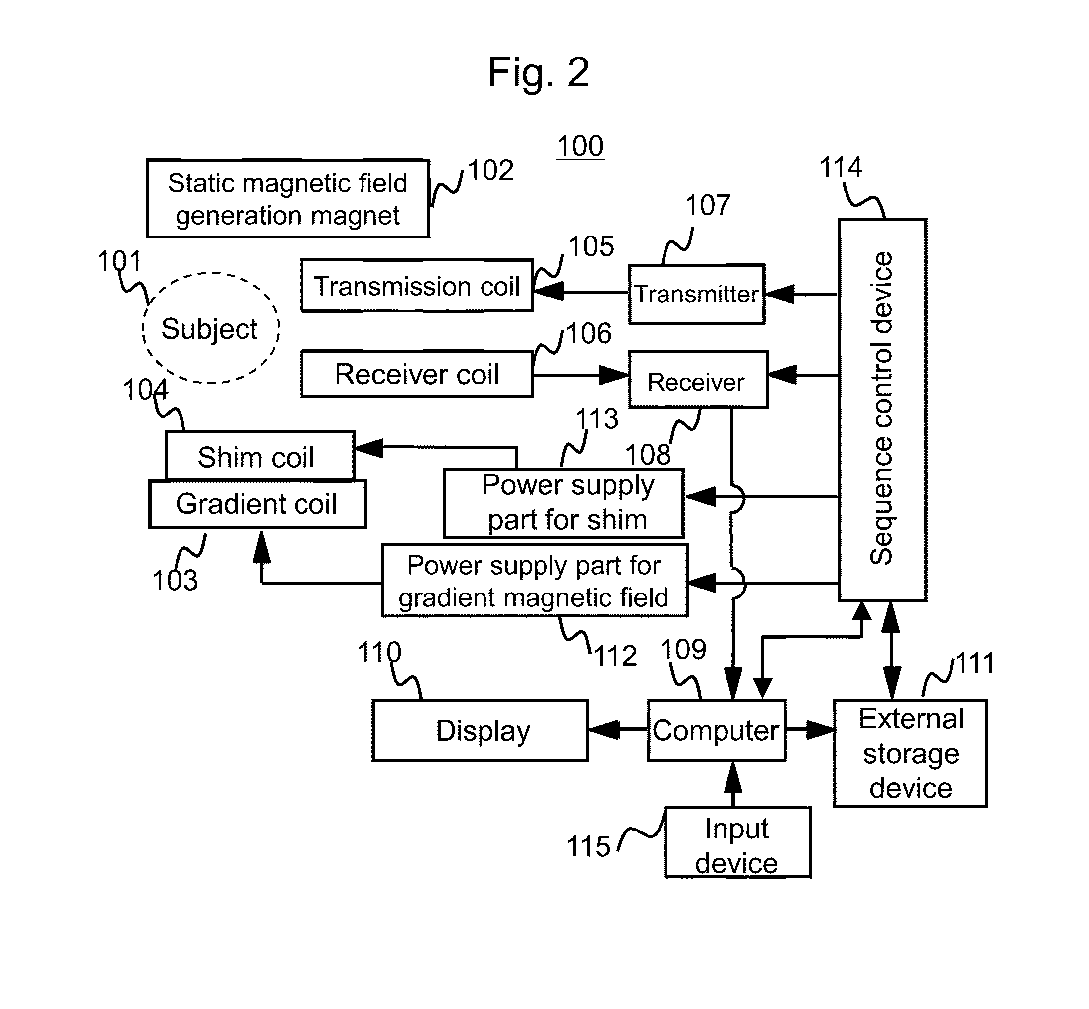
[0049]First, magnetic resonance imaging devices (MRI devices) according to this embodiment of the present invention will be explained. FIGS. 1A to 1C are exterior views of MRI devices according to this embodiment. FIG. 1A shows an MRI device 100 of the horizontal magnetic field type utilizing a tunnel-shaped magnet that generates a static magnetic field with a solenoid coil. FIG. 1B shows an MRI device 120 of the vertical magnetic field type utilizing a hamburger type (open type) magnet having separated upper and lower magnets, which are used for increasing spaciousness. Further, FIG. 1C shows an MRI device 130 utilizing a tunnel-shaped magnet similar to that shown in FIG. 1A, but depth of the magnet is shortened and the magnet is leaned t...


PUM


Abstract

An object of the present invention is to suppress artifacts generated by correction of spectral distortion induced by eddy currents in MRI devices with a simple method, and thereby improve accuracy of the correction. In the eddy current correction processing for correcting spectral distortion caused by an eddy current using phase values of FID signals of a substance showing higher signal intensities compared with a metabolite as an object of measurement, phase jumps of the phase values used for the correction are corrected beforehand. In the correction of the phase jumps, small phase change amount points are identified by using primary time differential values of the phase values, and the other points are identified as a phase jump generation region. Then, the primary time differential values corresponding to the identified phase jump generation regions are excluded. The phase jump generation regions are identified as regions where the primary time differential value changes in an amount not smaller than a threshold value defined beforehand within a range defined beforehand.

Description

TECHNICAL FIELD[0001]The present invention relates to spectroscopic imaging, especially an eddy current correction technique therefor for correcting spectral distortion induced by eddy current and so forth.BACKGROUND ART[0002]In magnetic resonance signals measured in MRI, there is observed the chemical shift phenomenon, which means small differences of resonance frequency originated in difference in molecular structure. There are known MRS (Magnetic Resonance Spectroscopy), in which magnetic resonance signals are separated for every molecule (metabolite) by using the chemical shift phenomenon to obtain spectra, as well as CSI (Chemical Shift Imaging) and MRSI (Magnetic Resonance Spectroscopic Imaging), in which spatial signal intensity distribution is imaged for every metabolite.[0003]Major metabolites of human bodies detectable by MRS or MRSI include choline (Cho), creatine (Cr), N-acetylaspartic acid (NAA), lactic acid (Lac), and so forth. Amounts of these metabolites enable stage...

Claims


Application Information

Patent Timeline
IPC IPC(8): G01R33/46
CPCG01R33/56518G01R33/4625A61B5/055G01R33/485
Inventor SHIRAI, TORUBITO, YOSHITAKAHIRATA, SATOSHISOUTOME, YOSHIHISA
Owner FUJIFILM HEALTHCARE CORP
Learn More