Display control device and method of controlling display device

Active Publication Date: 2020-12-31
LG DISPLAY CO LTD
View PDF0 Cites 1 Cited by
  • Summary
  • Abstract
  • Description
  • Claims
  • Application Information

AI Technical Summary

Benefits of technology

[0007]An object of the present disclosure is to provide a display control device and a method of controlling a display device whe

Problems solved by technology

However, in an image such as a star sky, a bright light of a night view, etc., where some pixels such as one pixel or several pixels locally have a rel

Method used


Image

  • Display control device and method of controlling display device
  • Display control device and method of controlling display device
  • Display control device and method of controlling display device

Examples


Example

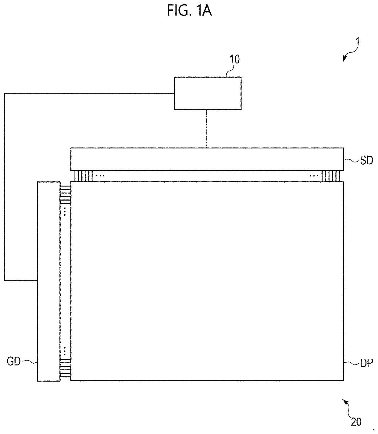
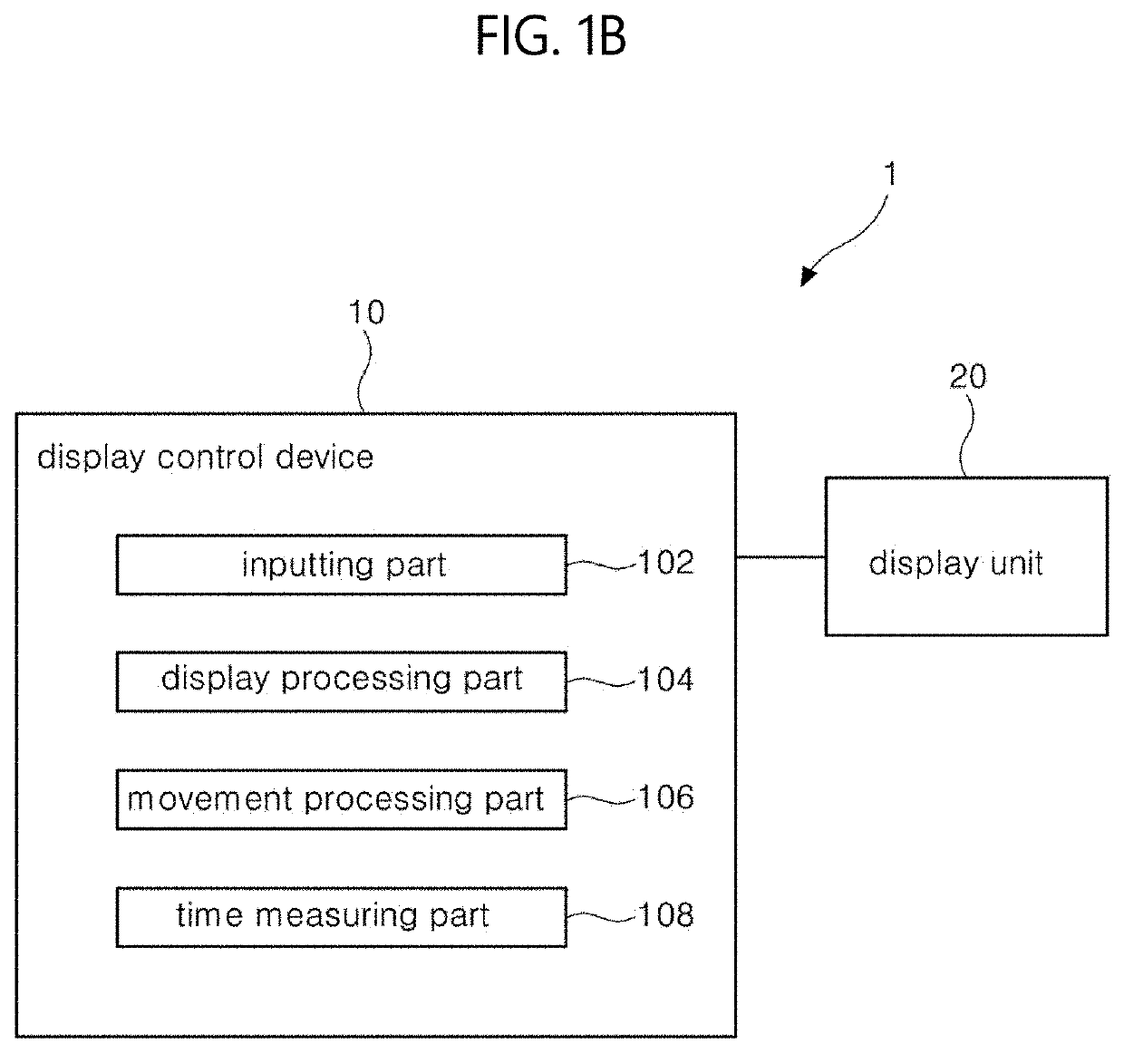
[0034]In FIG. 1A, a display device 1 according to a first embodiment of the present disclosure includes a display control device 10 and a display unit 20. In the display device 1, the display unit 20 displays an image corresponding to an image signal according to a control of the display control device 10. The display device 1 receives the image signal from an external system. In another embodiment, the display device 1 may include a display unit displaying an image using an image signal generated from an internal system. For example, the display device 1 may be used as an image output device of a computer, a television, an electric scoreboard, an electric sign terminal, a kiosk terminal, a smart phone, a tablet terminal, a portable phone, a digital still camera, a digital video camera, a game console, etc. In addition, other suitable devices capable of incorporating a display may be utilized and a person skilled in the art would readily appreciate other devices may be used beyond t...

Example

[0082]In a display control device according to a second embodiment of the present disclosure, the movement processing part 106 may calculate and determine the shift position using various equations other than the equations (2-1) and (2-2). For example, the movement processing part 106 may calculate and determine the shift position (xk, yk) using equations (3-1) and (3-2).

Equation 3-1

xk=round(rk·cos θk)  (3-1)

Equation 3-2

yk=round(rk·cos θk)  (3-2)

[0083]Here, γk and θk are defined by equations (3-3) and (3-4).

Equation3-3rk=10.5·Rk1 / 2(3-3)Equation3-4θk=2π·Rk′(3-4)

[0084]When the equations (3-1) and (3-2) are used, the movement processing part 106 calculates and determines the shift position (xk, yk) where the kth image moves independently on the shift position (xk−1, yk−1) where the (k−1)th image moves. The movement processing part 106 moves the image independently on the display position before the movement of the image.

[0085]The distribution of the accumulated display time where the a...


PUM


Abstract

A display control device includes: a display processing part displaying an image in a display unit; and a movement processing part changing a display position of the image according to a display time of the image within a movement range having a reference display position of the image in the display unit as a center, wherein the movement processing part changes the display position within the movement range such that an accumulated display time of the image is reduced from the center to a periphery of the movement range.

Description

CROSS REFERENCE TO RELATED APPLICATIONS[0001]The present application claims the priority benefit of Japanese Patent Application No. 2019-119646 filed in the Japan Patent Office on Jun. 27, 2019, which is hereby incorporated by reference in its entirety for all purposes as if fully set forth herein.BACKGROUNDTechnical Field[0002]The present disclosure relates to a display control device and a method of controlling a display device.Description of the Related Art[0003]In a display device such as an organic light emitting diode (OLED) display device, a plasma display panel (PDP) device, a cathode ray tube (CRT) display, a liquid crystal display (LCD) device, etc., there exists a phenomenon, which is referred to as a ‘burn-in,’ that a function displaying an image is deteriorated when an equal image is displayed for a long time period. As a technology preventing the burn-in, a technology where a display position of an image in a display unit is changed as a time elapses. See patent docume...

Claims


Application Information

Patent Timeline
IPC IPC(8): G09G3/3225
CPCG09G2340/0464G09G3/3225G09G3/20G09G3/007G09G2320/046G09G2320/048G09G2320/103G09G5/22G09G2320/062
Inventor TAKASUGI, SHINJI
Owner LG DISPLAY CO LTD
Why Eureka
Try Eureka