Eureka AIR delivers breakthrough ideas for toughest innovation challenges, trusted by R&D personnel around the world.

Electromagnetic conveyor with weighing station

Active Publication Date: 2021-01-07
B&R IND AUTOMATION GMBH
View PDF0 Cites 0 Cited by
  • Summary
  • Abstract
  • Description
  • Claims
  • Application Information

AI Technical Summary

Benefits of technology

The invention allows for weighing of objects while they are still moving on a conveyor belt. This is possible because the object is lifted off the belt by a mover as it moves through the weighing station, without interrupting the movement of the object. The weighing can be done using multiple weigh cells and the weights obtained can be averaged to determine the weight of the object. This invention results in increased weighing accuracy and flexibility in application.

Problems solved by technology

The issue with such weighing stations is that the continuity of the main conveyor is broken and that extra drive trains, bearings and guide elements are introduced by the weighing station which are additional wear items that require maintenance.
The disadvantage of this arrangement is that the weight of the conveyor section and of the mover that carries the object is also weighed by the weigh cell.
The weight of the conveyor section can be (much) higher than the weight of the object, making the weighing process less accurate and requiring a weigh cell suitable for higher weights.
This approach requires a great number of movers each equipped with a weigh cell which increases the costs and complexity of the checkweigher.

Method used


Image

  • Electromagnetic conveyor with weighing station
  • Electromagnetic conveyor with weighing station
  • Electromagnetic conveyor with weighing station

Examples


Embodiment Construction

[0021]The particulars shown herein are by way of example and for purposes of illustrative discussion of the embodiments of the present invention only and are presented in the cause of providing what is believed to be the most useful and readily understood description of the principles and conceptual aspects of the present invention. In this regard, no attempt is made to show structural details of the present invention in more detail than is necessary for the fundamental understanding of the present invention, the description taken with the drawings making apparent to those skilled in the art how the several forms of the present invention may be embodied in practice.

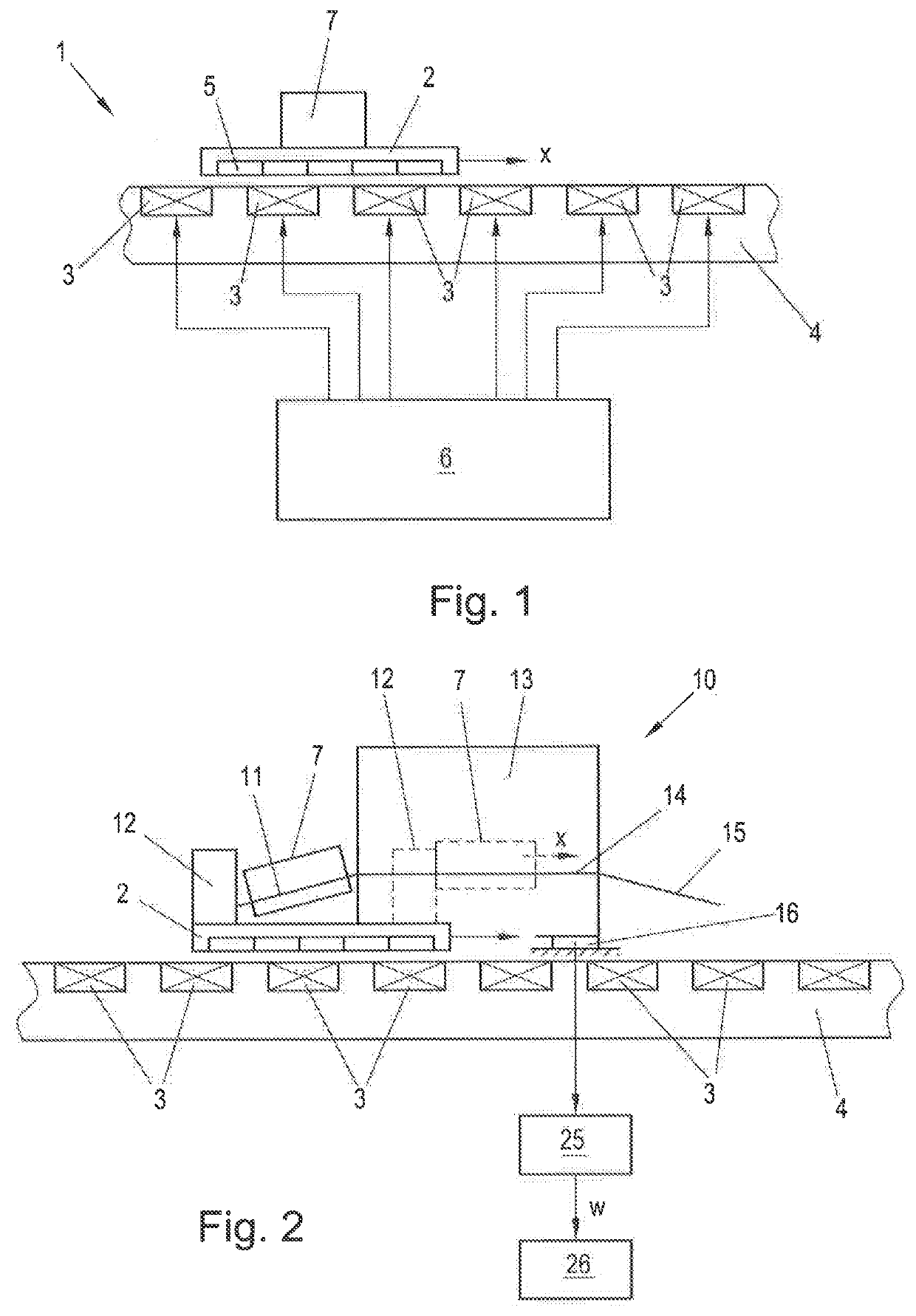
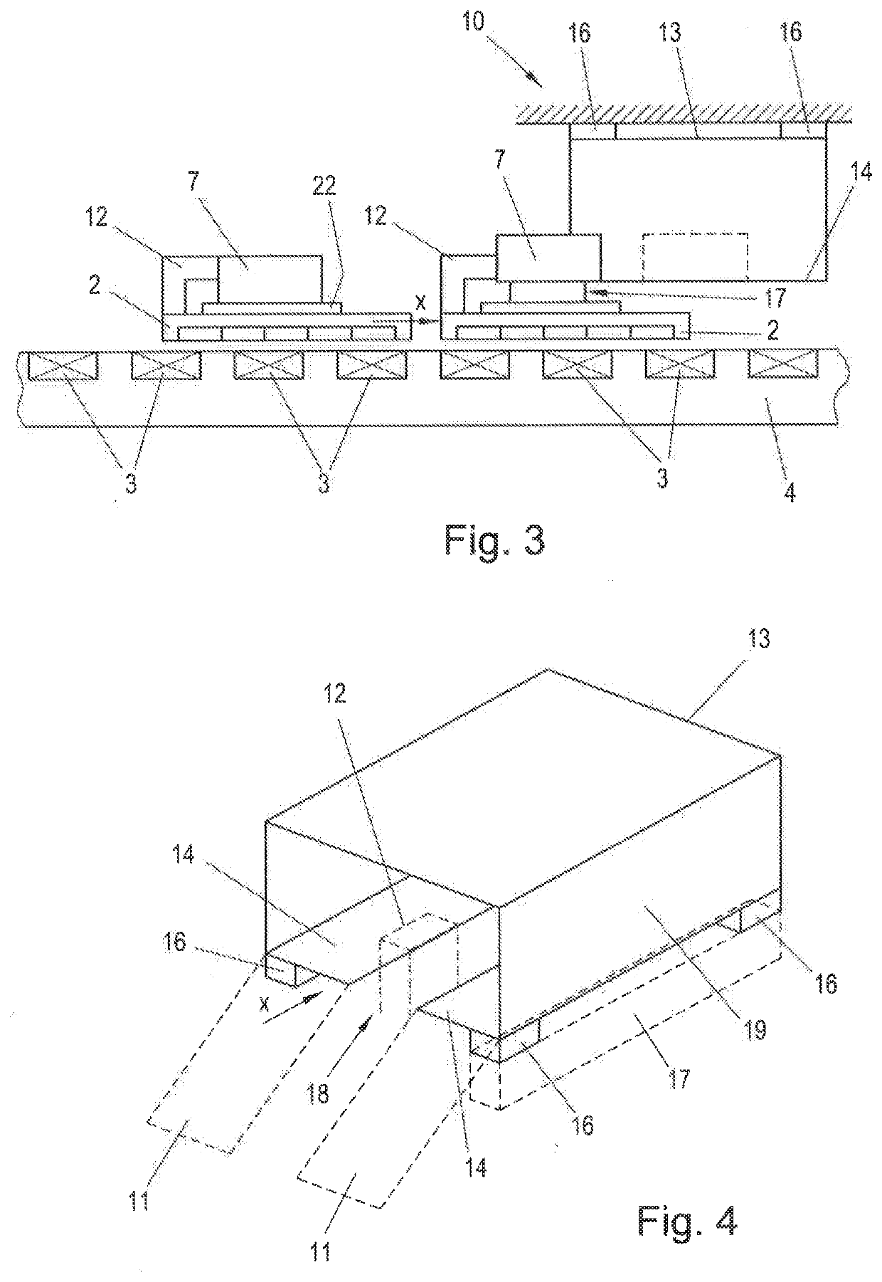
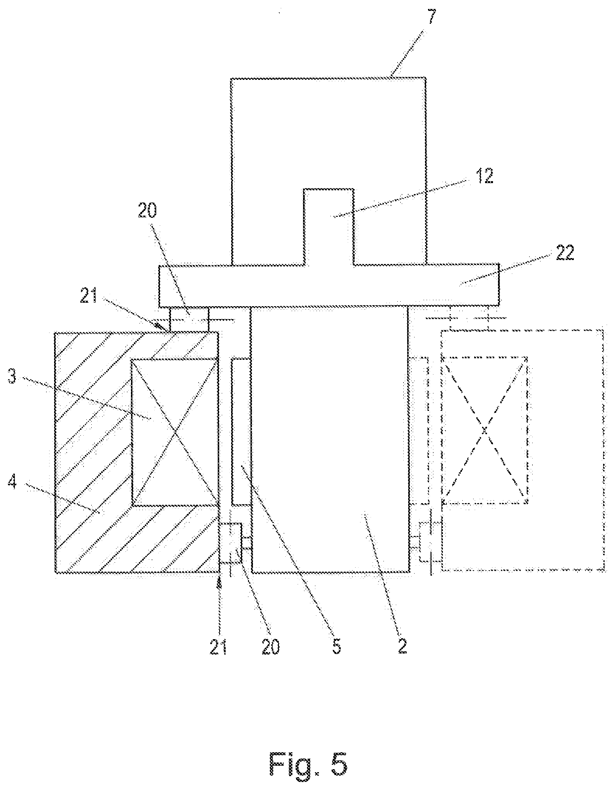
[0022]Electromagnetic conveyors are well known, e.g. as linear motors or planar motors. Such electromagnetic conveyors have a stationary part comprising a plurality of stationary arranged drive coils. The stationary part forms the stator of the electromotor and a track along which a mover of the electromagnetic conveyor m...


PUM


Abstract

Method for weighing an object transported on a mover of an electromagnetic conveyor and electromagnetic conveyor. Method includes lifting object off the mover with a lifting device; setting down object onto at least one transport plane of a weighing station arranged at a weighing region of the track and arranged on at least one weigh cell. The transport plane extends in the direction of movement to support the object when in the weighing station. The method also includes actively driving object while lifted off from the mover and while supported on the transport plane with the mover as it moves along the track through a weighing region; weighing object with at least one weigh cell while the object is supported by the transport plane; and setting down object on the mover after weighing in the weighing station for onward movement of object along the track with the mover.

Description

BACKGROUND1. Field of the Invention[0001]Embodiments relate to a method and arrangement for weighing an object that is transported on a mover of an electromagnetic conveyor, whereas the mover is moved along a stationary track of the electromagnetic conveyor in a direction of movement.2. Discussion of Background Information[0002]In many manufacturing and production plants and processes objects (e.g. products, containers etc.) are moved along certain transportation routes via conveyors. Conveyors can for example be conventional conveyor belts but also electromagnetic conveyors, such like long stator linear motors or planar motors. In manufacturing and production processes it is often necessary to weigh the moved objects. This is typically done via weighing stations, e.g. inline checkweighers, that are arranged at the required positions along the conveying route. Such weighing stations are normally standalone pieces of equipment with a small section of conveyor built into it. The objec...

Claims


Application Information

Patent Timeline
IPC IPC(8): G01G11/00B65G54/02G01G11/04
CPCG01G11/003G01G11/04B65G54/02B65G35/00G01G19/52G01G19/03
Inventor DERRICK, STACEY
Owner B&R IND AUTOMATION GMBH
Why Eureka
Eureka Blog
Learn More