Locking assembly

a technology of locking assembly and locking plate, which is applied in the field of locking assembly, can solve the problems of easy theft, unattended electronic devices, and difficulty for users to use restrooms or purchase refreshments, and achieve the effects of quick and efficient use, quick and easy locking and unlocking, and quick and easy clamping

Active Publication Date: 2021-01-14
TECHLOK SOLUTIONS LLC
View PDF0 Cites 3 Cited by
  • Summary
  • Abstract
  • Description
  • Claims
  • Application Information

AI Technical Summary

Benefits of technology

[0008]The subject invention is directed to a locking assembly for locking a portable electronic device to a work surface. The locking assembly includes a clamp assembly having an elongated bar extending between a first end and a second end and a first jaw and a second jaw, with at least one of the first jaw or the second jaw moveable along the elongated bar between the first end and the second end for clamping a work surface between the first and second jaws. A locking mechanism is further included for selectively locking the relative positioning between the first jaw and the second jaw (i.e., securing the work surface between the first and second jaws in an un-movable / locked condition). The locking assembly further includes a connector extending from a first connector end pivotally connected to one of the clamp assembly or locking mechanism to a second connector end for connection to a provided portable electronic device. The connector thus secures the portable electronic device to the work surface while permitting the portable electronic device to pivot with respect to the locking assembly while locked thereto. In use, the second connector end is intended to be connected to the portable electronic device which a user desires to secure or lock to the locking assembly and the first connector end can be quickly locked and unlocked from the locking assembly for quick and efficient use.
[0009]I accordance with another aspect, the subject invention is directed to locking assembly for locking a portable electronic device to a work surface. The locking assembly includes a clamp assembly having an elongated bar extending between a first end and a second end and a first jaw and a second jaw, with at least one of the first jaw or the second jaw moveable along the elongated bar between the first end and the second end for clamping a work surface between the first and second jaws. A locking mechanism is further included for selectively locking the relative positioning between the first jaw and the second jaw (i.e., securing the work surface between the first and second jaws in an un-movable / locked condition). Movement of the locking mechanism results in movement of the first jaw or the second jaw into forceful contact with the work surface. The clamp assembly can therefore be quickly and easily clamped to the work surface. Movement of the locking mechanism is pivotal and results in a leveraged lesser movement of the first jaw or second jaw for a stronger clamping force.

Problems solved by technology

Once situated, however, it can be difficult for the user to use a restroom or purchase refreshments without leaving their portable electronic device unattended and vulnerable to theft.
In fact, occurrences of theft have become so common that many shops and stores have started displaying signs warning clientele not to leave their portable electronic devices unattended.
However, despite some success, the prior art locking devices still exhibit common shortcomings.
For example, prior art locking devices have struggled to provide a “one-size-fits-all” solution.
More specifically, the prior art locking devices can only be used with portable electronic devices and work surfaces having very specific dimensions and configurations, and deviation from these dimensions and configurations result in damage to a work surface when trying to lock a non-compliant portable electronic device.
In addition, prior art locking devices oftentimes employ rigid clamping mechanisms that are both cumbersome and relatively easy to compromise with simple tools or by simply repeated wiggling and pulling on the clamping mechanism.

Method used


Image

  • Locking assembly
  • Locking assembly
  • Locking assembly

Examples


Embodiment Construction

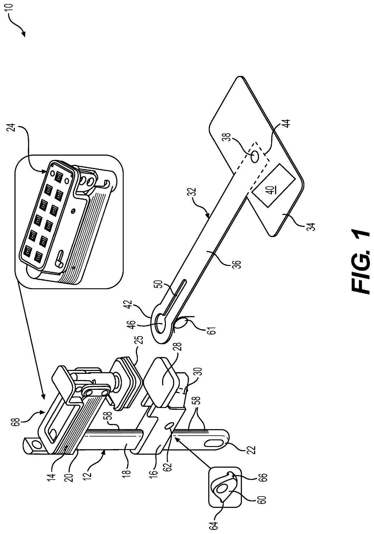
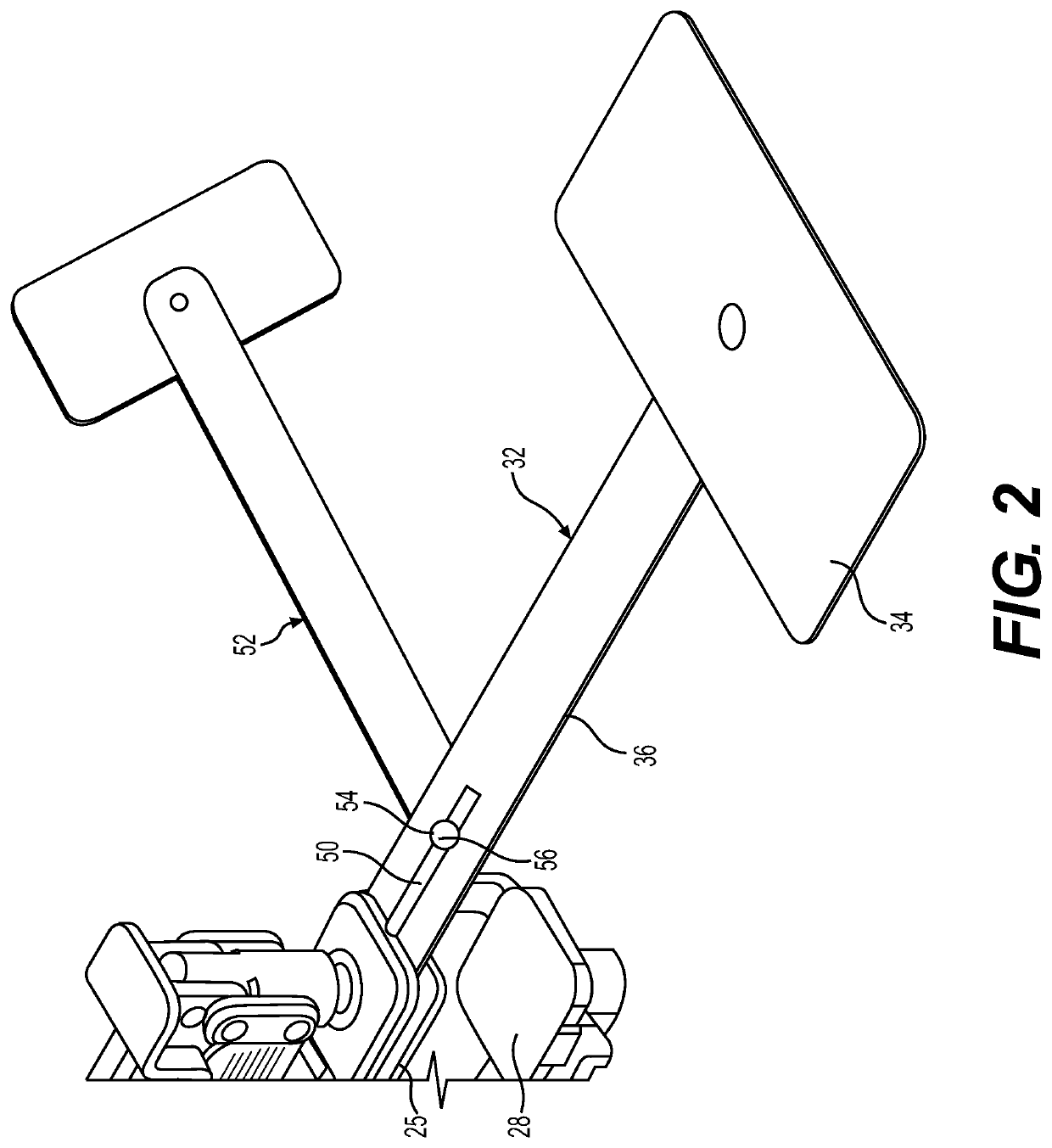
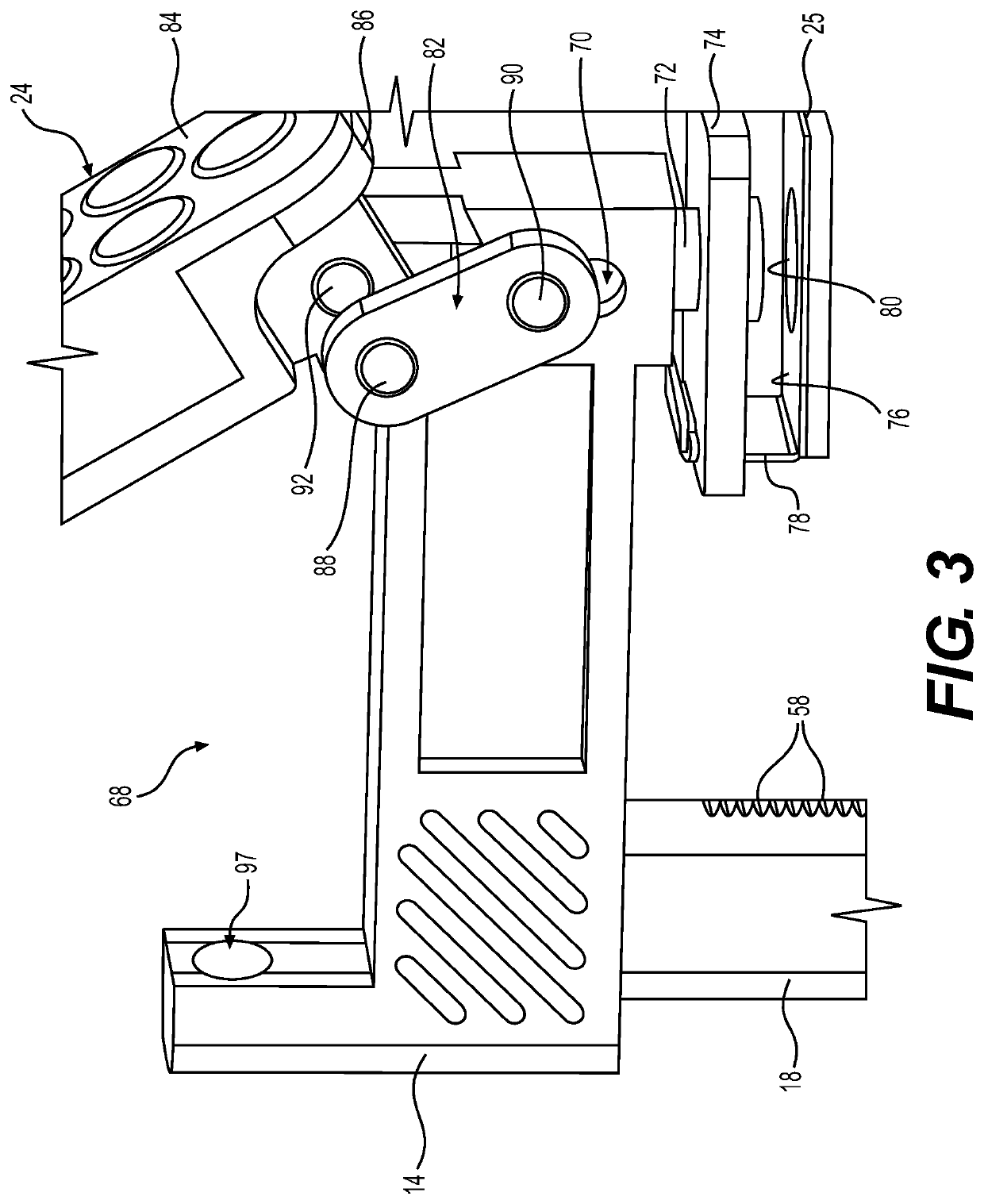
[0034]Example embodiments will now be described more fully with reference to the accompanying drawings. In general, the subject embodiments are directed to a locking assembly for securing portable electronic devices to a work surface. However, the example embodiments are only provided so that this disclosure will be thorough, and will fully convey the scope to those who are skilled in the art. Numerous specific details are set forth such as examples of specific components, devices, and methods, to provide a thorough understanding of embodiments of the present disclosure. It will be apparent to those skilled in the art that specific details need not be employed, that example embodiments may be embodied in many different forms and that neither should be construed to limit the scope of the disclosure. In some example embodiments, well-known processes, well-known device structures, and well-known technologies are not described in detail.

[0035]Referring to the Figures, wherein like numer...


PUM


Abstract

A locking assembly for locking a portable electronic device to a work surface. The locking assembly comprises a clamp assembly including an elongated bar that extends between a first end and a second end. The clamp assembly further includes a first jaw and a second jaw moveable along the elongated bar for clamping to a work surface between the first and second jaws. A connector extends from a first connector end that is pivotally connected to the locking assembly to a second end that can be connected to the portable electronic device. The connector securing the portable electronic device to the work surface while permitting it to pivot with respect to the locking assembly.

Description

CROSS-REFERENCE TO RELATED APPLICATION[0001]This U.S. patent application claims priority to and the benefit of U.S. provisional application No. 62 / 871,764 filed on Jul. 9, 2019, the entire disclosure of which is incorporated herein by reference.BACKGROUND OF THE INVENTION1. Field of the Invention[0002]The present invention relates to a locking assembly. More particularly, the present invention relates to a locking assembly for securing an unsupervised portable electronic device or other personal belongings to a work surface.2. Related Art[0003]This section provides background information related to the present disclosure which is not necessarily prior art.[0004]Since the introduction of the internet age, more opportunities have become available for persons to work remotely. With this availability, it has become a common practice to take and use portable electronic devices, such as laptops, in public places. For example, users of these portable electronic devices frequent coffee shop...

Claims


Application Information

Patent Timeline
Patent Type & Authority Applications(United States)
IPC IPC(8): B25B5/06B25B5/16
CPCB25B5/068B25B5/163F16M13/022F16M11/2007F16M11/40F16M11/04F16M11/06E05B73/0082E05B49/00E05B45/061G08B13/02G08B13/14F16M2200/02B25B5/102B25B5/166
Inventor ANGOTT, RYAN J.ANGOTT, PAUL G.LATCHA, MICHAEL A.
Owner TECHLOK SOLUTIONS LLC
Why Eureka
Try Eureka