
Method for leak testing a tank head before it enters service

a tank head and leak detection technology, applied in the direction of fluid tightness measurement, container discharge methods, instruments, etc., can solve the problems of relatively expensive test benches, relatively expensive and time-consuming, etc., to reduce investment, reduce the duration of testing operation, and reduce the duration of testing.

Pending Publication Date: 2021-01-14
ADVENTA
View PDF2 Cites 0 Cited by
  • Summary
  • Abstract
  • Description
  • Claims
  • Application Information

AI Technical Summary

Benefits of technology

The patent describes a method to check the sealing of tanks without needing to fill them with air. Instead, a small amount of gas is needed, which reduces the cost and duration of the testing process. This method also improves safety as it reduces the amount of gas needed and eliminates the need for a large tank.

Problems solved by technology

However, such an operation requires a test bench that is relatively expensive (an investment in the order of €1M), large quantities of gas to be pressurized (such as 35 m3 at atmospheric pressure for a 50-litre cylinder to be tested at 700 bar) and a test duration of at least 20 minutes per cylinder: all of which is relatively expensive and time-consuming.
The problem faced is thus that of being able to test the sealing at the fastening of said tank heads during the manufacture of the tank assemblies, after such a head has been fitted on each tank and before completely filling the latter, either for testing purposes or for being entered into service, of these tank assemblies (a tank assembly being formed by a tank or cylinder at least equipped with the tank head thereof), on the one hand without requiring an expensive test bench and without consuming large quantities of gas, especially when this gas is hydrogen, and on the other hand using a method that can be implemented in a relatively short time, i.e. less than 5′ per cylinder / tank.

Method used


Image

  • Method for leak testing a tank head before it enters service

Examples


Embodiment Construction

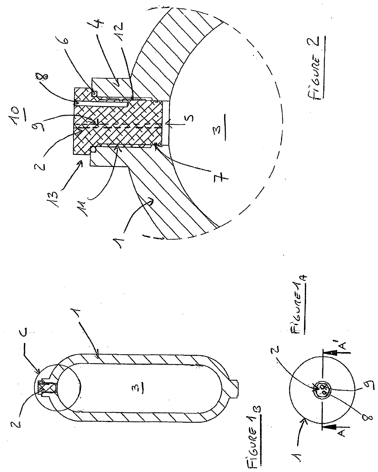
[0020]According to the representation shown in the figures, a tank head 2, intended to be filled with a high-pressure gas, is fastened, preferably by screwing 11, into a boss 4 located on the wall 1 of said tank and opening therein, said head 2 thus plugging the orifice 5 of this boss; which wall 1 delimits an inner chamber 3 capable of receiving the gas and is made of a material and has a thickness ensuring its ability to withstand the gas storage pressure such as up to at least 100 bar, and even 300 bar, or up to at least 700 bar for hydrogen.

[0021]This tank head 2 can include, depending on the uses, various ducts (such as that 9 shown in FIGS. 1A and 2 and opening out onto the top of the head 2), which pass through the thickness of the head 2 from end to end and which bring the chamber 3 into communication with the outside 10 and which thus receive, at the end thereof opening out to the outside, piping connectors, closure plugs, valves, etc.

[0022]This tank head 2 comprises at lea...


PUM


Abstract

Method for leak testing a tank head, intended to be filled with a gas under high pressure and before it enters service, which head including at least two sealing devices, referred to as an inner and an outer sealing devices, which delimit there between an intermediate space into which opens a duct which communicates with the outside, such that: said test is carried out during the manufacture of the tank assembly, after fitting the tank head and before this tank is filled with high-pressure gas, pressurized gas is injected via the duct into the intermediate space between the two sealing devices, the gas injection is stopped at a given pressure, the value of said pressure is measured via said duct

Description

TECHNICAL FIELD[0001]The present disclosure relates to a method for leak testing a tank head before it enters service. The technical field of the disclosure is that of the manufacture of tank assemblies and gas cylinders capable of containing and supplying pressurized gas, even high-pressure gas, in particular such as hydrogen, by way of a tank head fastened to a boss on the tank.BACKGROUND[0002]During the manufacture of tank assemblies and after such a head has been fitted on each tank, the sealing at the fastening, generally carried out by screwing, of said tank heads must be tested to prevent any subsequent leak when the tanks are filled with gas, especially when this gas is hydrogen.[0003]For this purpose, a known method involves filling each tank or gas cylinder up to the predetermined test pressure, then testing whether this pressure is maintained for a duration that is sufficient to conclude that there are no leaks. However, such an operation requires a test bench that is rel...

Claims


Application Information

Patent Timeline
Patent Type & Authority Applications(United States)
IPC IPC(8): G01M3/32F17C13/00
CPCG01M3/3209F17C2223/036F17C2205/0302F17C13/002F17C13/00F17C2201/0109F17C2201/056F17C2201/058F17C2203/0617F17C2205/0305F17C2221/012F17C2223/0123F17C2260/023F17C2260/038Y02E60/32
Inventor MUSSOT, JEAN-LUCLABROT, OLIVIER
Owner ADVENTA
Learn More