Supercharge Your Innovation With Domain-Expert AI Agents!

Method for detection of laser reflectors for mobile robot localization and apparatus for the same

a technology for mobile robots and laser reflectors, applied in the field of local detection of laser reflectors for mobile robots, can solve the problems of difficult maintenance, limited stability of the technology to apply a natural marker-based localization technology, and the increase in the cost of installing barcodes or rfid tags, so as to achieve the effect of accurately detecting only the actual reflector

Inactive Publication Date: 2021-01-14
ELECTRONICS & TELECOMM RES INST
View PDF1 Cites 0 Cited by
  • Summary
  • Abstract
  • Description
  • Claims
  • Application Information

AI Technical Summary

Benefits of technology

The patent aims to use information from a laser scanner and predefined reflectors to accurately detect only the actual reflector from a variety of objects made of similar materials. The technical effect is to improve the accuracy of detecting objects that reflect laser light.

Problems solved by technology

However, there is a limit in terms of stability of the technology to apply a natural marker-based localization technology developed in academic research in the dynamic environment required by the real industrial domain.
Among the artificial marker-based localization method, the method of attaching barcodes or RFID tags to the floor or walls can be recognized accurately at low cost, but it is difficult to maintain due to damage caused by physical contact with surrounding users and robots Moreover, the cost of installing barcodes or RFID tags increased significantly as die range of robot applications expands.
Also, the method of specially-designed markers on die ceiling may be difficult to attach depending on the structure of the ceiling, and may require separate device to detect the special markers.
For example, materials such as glass, steel, white walls, etc. have very high laser reflectivity, so it is difficult to accurately distinguish only laser reflectors by setting the boundary values.

Method used

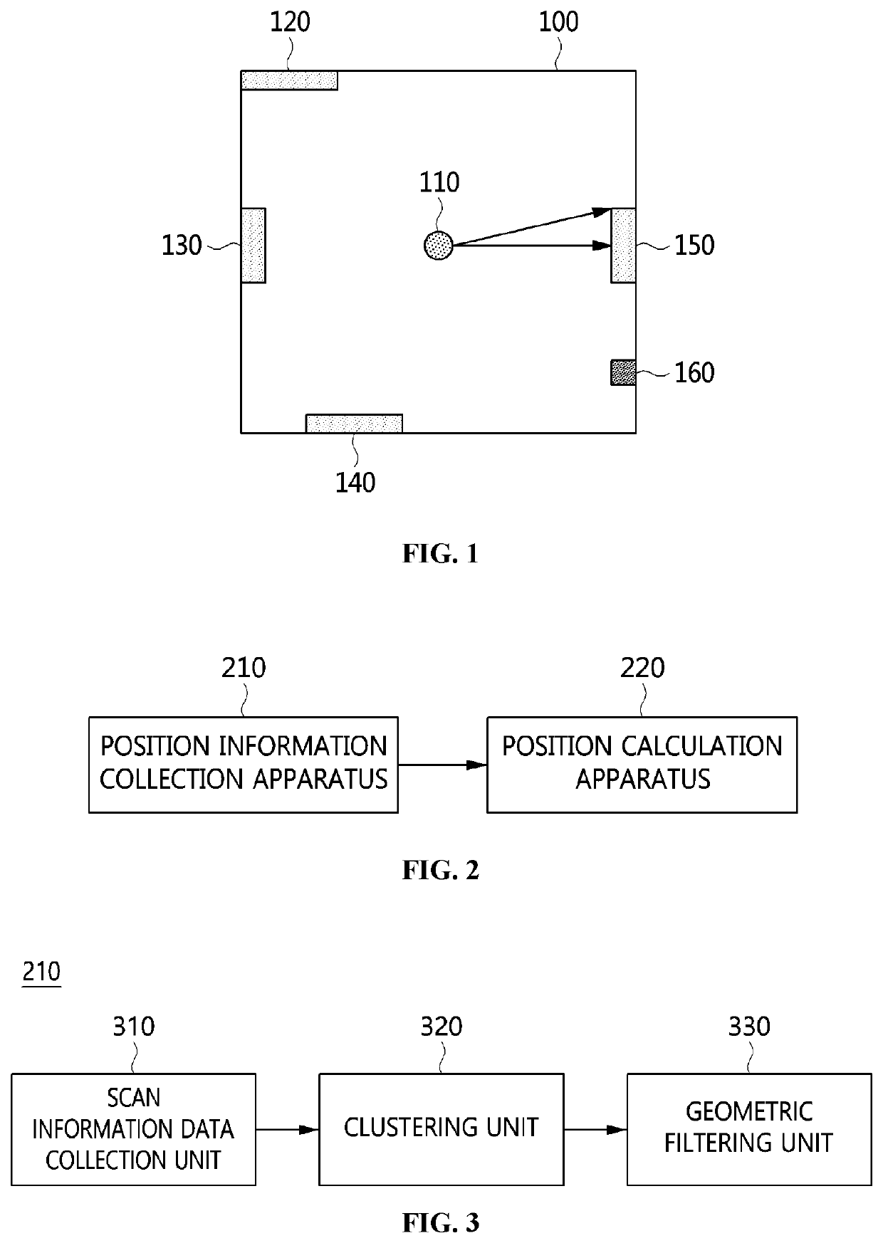
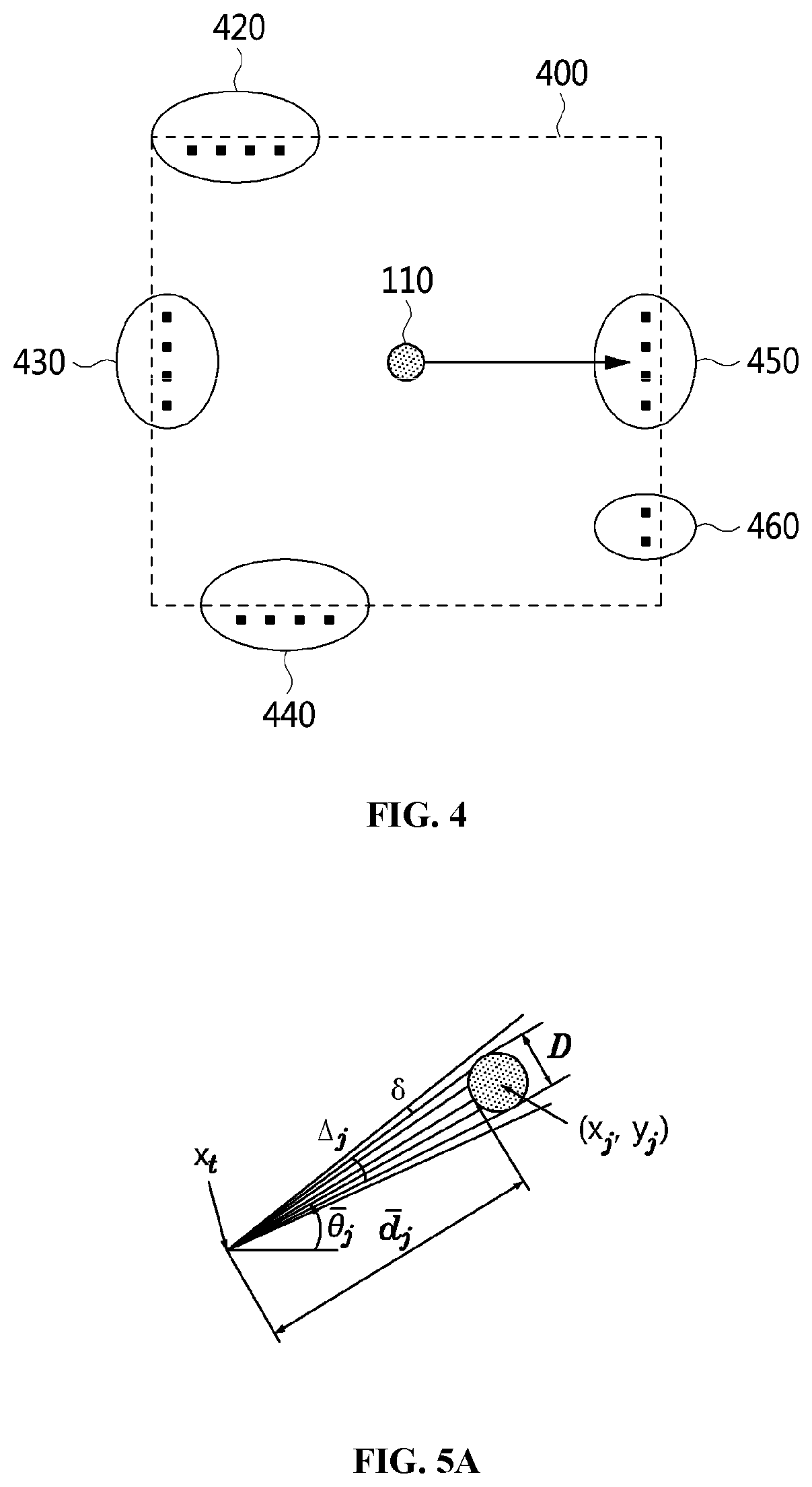
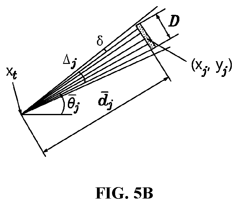

Image

  • Method for detection of laser reflectors for mobile robot localization and apparatus for the same
  • Method for detection of laser reflectors for mobile robot localization and apparatus for the same
  • Method for detection of laser reflectors for mobile robot localization and apparatus for the same

Examples


Embodiment Construction

[0041]The advantages and features of the present invention and methods of achieving them will be apparent from the following exemplary embodiments to be described in more detail with reference to the accompanying drawings. However, it should be noted that the present invention is not limited to the following exemplary embodiments, and may be implemented in various forms. Accordingly, tire exemplary embodiments are provided only to disclose the present invention and to let those skilled in the art know the category of the present invention, and the present invention is to be defined based only on the claims. The same reference numerals or the same reference designators denote the same elements throughout the specification.

[0042]It will be understood that, although the terms “first,”“second,” etc. may be used herein to describe various elements, these elements are not intended to be limited by these terms. These terms are only used to distinguish one element from another element. For ...


PUM


Abstract

Disclosed herein is a method for detecting laser reflectors for mobile robot localization. The method includes collecting scan information data corresponding to positions of surrounding objects using a laser scanner mounted on a mobile robot; generating a reflector cluster based on reflection intensities of the scan information data; classifying the reflector cluster into individual reflector clusters, each of the individual reflector clusters corresponding to each of the laser reflectors; determining whether each of the individual reflector clusters is a valid individual reflector cluster corresponding to an actual individual laser reflector or not based on geometric filtering on die each of the individual reflector clusters; and calculating position of the actual individual laser reflector based on at least one of the scan information data corresponding to the valid individual reflector cluster.

Description

CROSS REFERENCE TO RELATED APPLICATION[0001]This application claims the benefit of Korean Patent Nos. 10-2019-0083711, filed Jul. 11, 2019 and 10-2020-0063100, filed May 26, 2020, which are hereby incorporated by references in their entireties into this application.BACKGROUND OF THE INVENTION1. Technical Field[0002]The present invention relates to a method for detecting laser reflectors for mobile robot localization in the dynamic environment and an apparatus for the same.2. Description of the Related Art[0003]With the recent development of self-driving technologies, mobile robots are being used in various places ranging from public places to dangerous environments, such as hospitals, nuclear power plants, factories and warehouses. However, accurate location recognition (localization) technology must be preceded to operate and apply reliably autonomous driving technology to more diverse real-life situations.[0004]Previous academic research focused on developing localization technolo...

Claims


Application Information

Patent Timeline
IPC IPC(8): G01S7/481G01S17/931G05D1/02
CPCG01S7/4817G05D1/0259G01S17/931G01S17/42G01S7/4808G05D1/0236
Inventor LEE, YU-CHEOLYU, WON-PIL
Owner ELECTRONICS & TELECOMM RES INST
Features
  • R&D
  • Intellectual Property
  • Life Sciences
  • Materials
  • Tech Scout
  • Unparalleled Data Quality
  • Higher Quality Content
  • 60% Fewer Hallucinations
Learn More