
Plasma control system and plasma control system program

a control system and plasma technology, applied in the direction of plasma technique, chemical vapor deposition coating, coating, etc., can solve the problems of non-uniform density of plasma inability to use, and inability to uniformize the amount of current along the longitudinal direction of the antenna

Active Publication Date: 2021-01-21
NISSIN ELECTRIC CO LTD
View PDF0 Cites 2 Cited by
  • Summary
  • Abstract
  • Description
  • Claims
  • Application Information

AI Technical Summary

Benefits of technology

The patent allows for the generation of a uniform plasma along the length of antennas, even when using large substrates with long antennas. This results in improved performance and reliability of the antennas.

Problems solved by technology

However, when the size of the substrate is large, a configuration in which relatively short antennas are disposed in four directions with respect to the substrate, which is as used in the plasma processing apparatus disclosed in Patent Literature 1, cannot be used.
As a result, a distribution of the amounts of currents along the longitudinal directions of the antennas is not able to be uniformized, and there is a problem in that the density of the plasma along the longitudinal direction of the antennas is non-uniform.

Method used


Image

  • Plasma control system and plasma control system program
  • Plasma control system and plasma control system program
  • Plasma control system and plasma control system program

Examples


second embodiment

[0121]In a plasma control system 200 according to a second embodiment, the configuration of a control apparatus X is different from that according to the embodiment described above.

[0122]More specifically, the control apparatus X according to the second embodiment, as illustrated in FIG. 11, has functions of a current value acquiring part X1, a pattern data storing part X6, an actual current value pattern determining part X7, a control part X4, and a control stopping part X5.

[0123]Hereinafter, each of the parts will be described. Since the current value acquiring part X1 and the control stopping part X5 have the same functions as those according to the embodiment described above, detailed description thereof will be omitted.

[0124]The pattern data storing part X6 is set to a predetermined area of a memory configuring the control apparatus X and stores pattern data in which a plurality of types of reference current value patterns representing magnitude relations between the first curr...


PUM

PropertyMeasurementUnit
frequencyaaaaaaaaaa
center angleaaaaaaaaaa
currentaaaaaaaaaa

Abstract

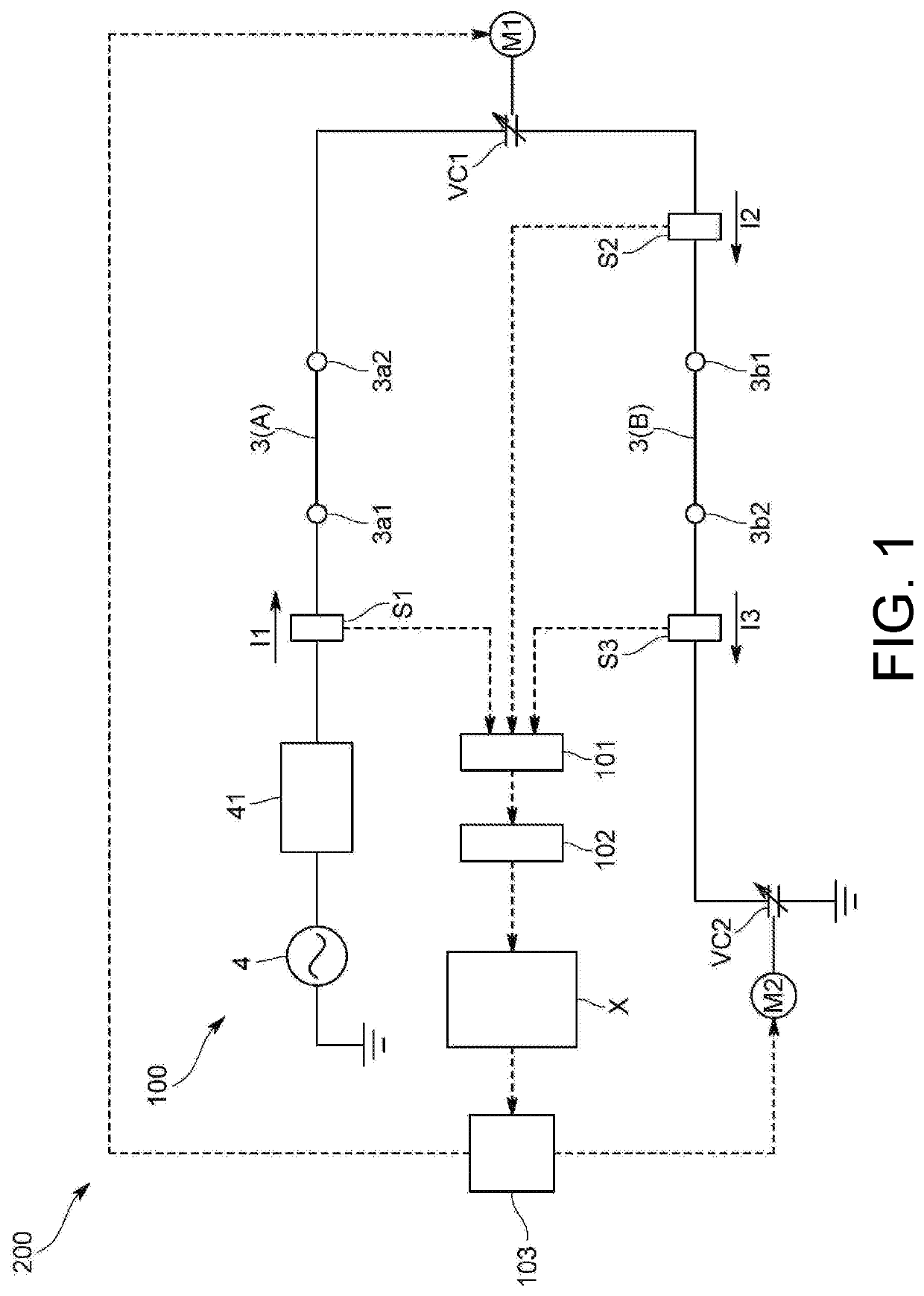
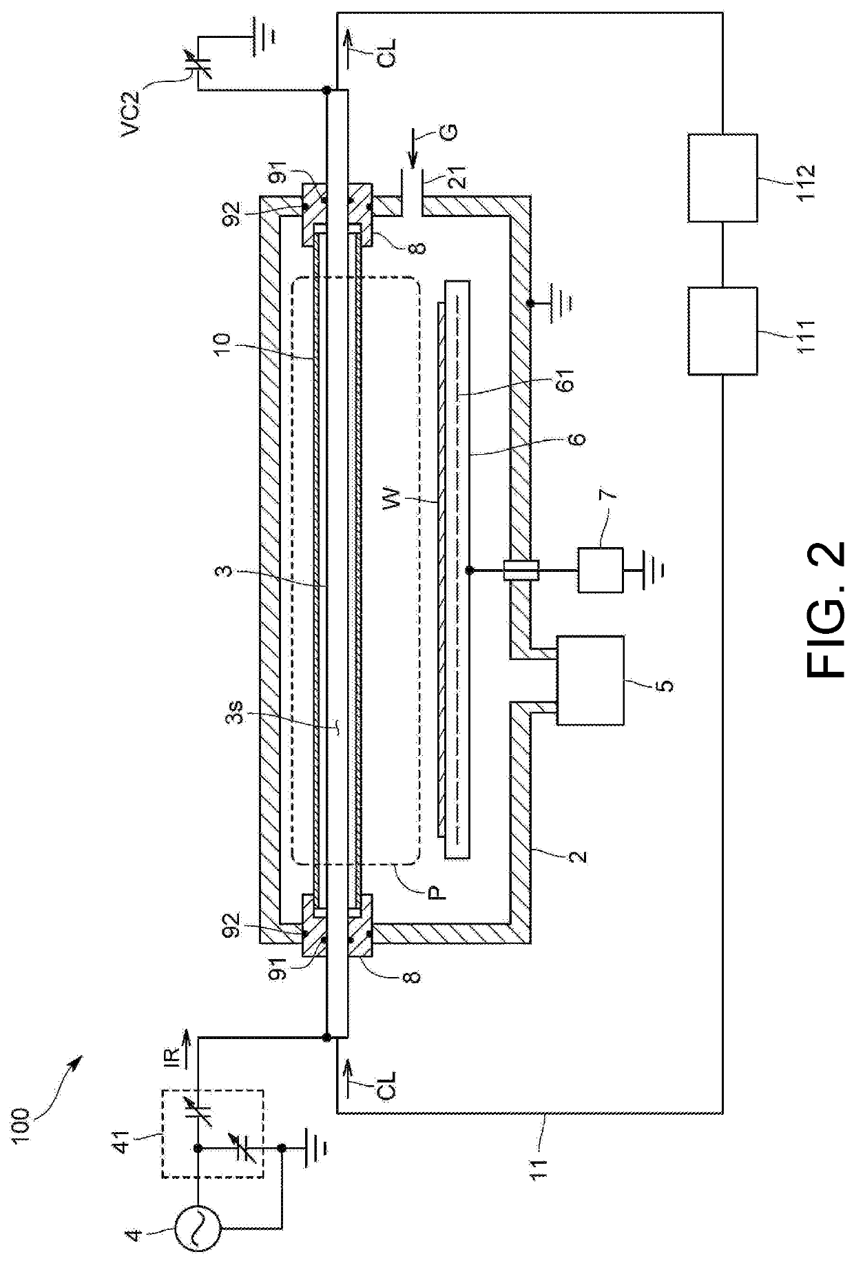
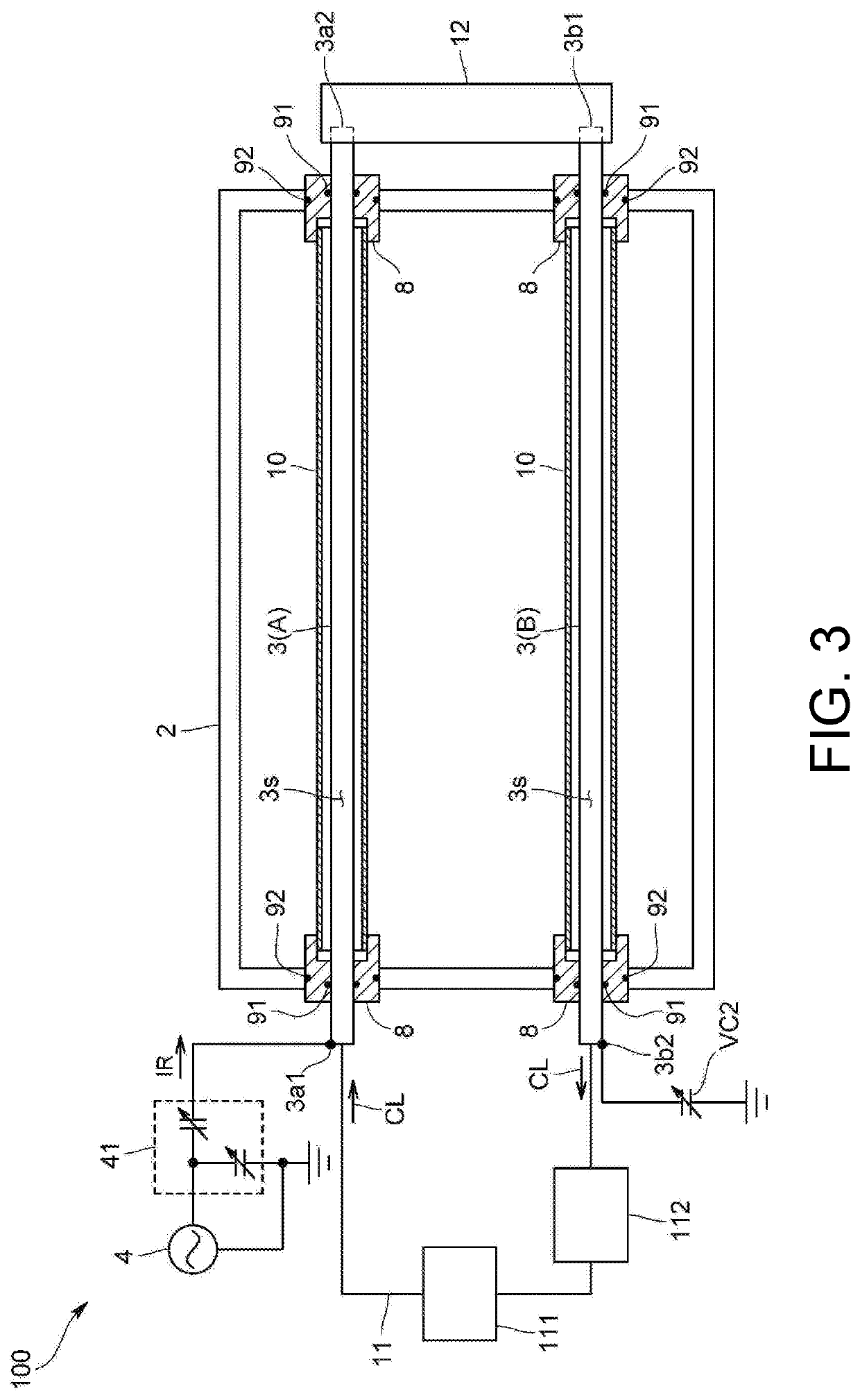
A plasma control system comprises: a high frequency power source; a first antenna connected at one end to the high frequency power source; a second antenna connected at one end to another end of the first antenna; a first variable reactance element provided between the first antenna and the second antenna; a first drive part for the first variable reactance element; a second variable reactance element connected to another end of the second antenna; a second drive part for the second variable reactance element; a first current detection part detecting the current in the one end of the first antenna; a second current detection part detecting the current between the first antenna and the second antenna; a third current detection part detecting the current in the other end of the second antenna; and a control device controlling the first drive part and the second drive part.

Description

TECHNICAL FIELD[0001]The present disclosure relates to a plasma control system controlling an inductively-coupled plasma generated by causing a high frequency current to flow through an antenna and a program used for this plasma control system.BACKGROUND ART[0002]As illustrated in Patent Literature 1, a plasma processing apparatus having a configuration in which an inductively-coupled plasma (abbreviated to ICP) is generated when a plurality of antennas are disposed in four directions with respect to a substrate inside a vacuum container, and a high-frequency current is caused to flow through such antennas is known.[0003]Described in more detail, this plasma processing apparatus includes variable impedance elements connected to the plurality of antennas and pickup coils or capacitors disposed on power supply sides of the plurality of antennas. By performing feedback control of impedance values of the variable impedance elements on the basis of output values from the pickup coils or ...

Claims


Application Information

Patent Timeline
Patent Type & Authority Applications(United States)
IPC IPC(8): H05H1/46H01J37/32
CPCH05H1/46H01J37/32183H05H2001/4667H05H2001/4675H01J2237/327C23C16/505H05H1/4652H05H2242/26H01J37/3211H05H1/466
Inventor IWAKOKE, TSUBASA
Owner NISSIN ELECTRIC CO LTD
Learn More