
Proportional valve for controlling a gaseous medium

a gaseous medium and proportional valve technology, applied in the direction of valve operating means/release devices, electrochemical generators, magnetic bodies, etc., can solve the problems of low magnetic flux leakage at the thin-walled cylindrical web and only a slight influence of magnetic flux through the web

Active Publication Date: 2021-01-28
ROBERT BOSCH GMBH
View PDF0 Cites 3 Cited by
  • Summary
  • Abstract
  • Description
  • Claims
  • Application Information

AI Technical Summary

Benefits of technology

The invention is a valve that controls the release of gas, specifically hydrogen. The valve is designed so that the part that controls the valve and the part that generates the magnetic field are all in one piece. This design helps to make the valve work better. This patent is useful for people who work with gas control systems.

Problems solved by technology

As a result, the magnetic flux leakage at the thin-walled cylindrical web is low, with the result that the magnetic flux through the web has only a slight influence on the stroke of the magnet armature.

Method used


Image

  • Proportional valve for controlling a gaseous medium
  • Proportional valve for controlling a gaseous medium
  • Proportional valve for controlling a gaseous medium

Examples


Embodiment Construction

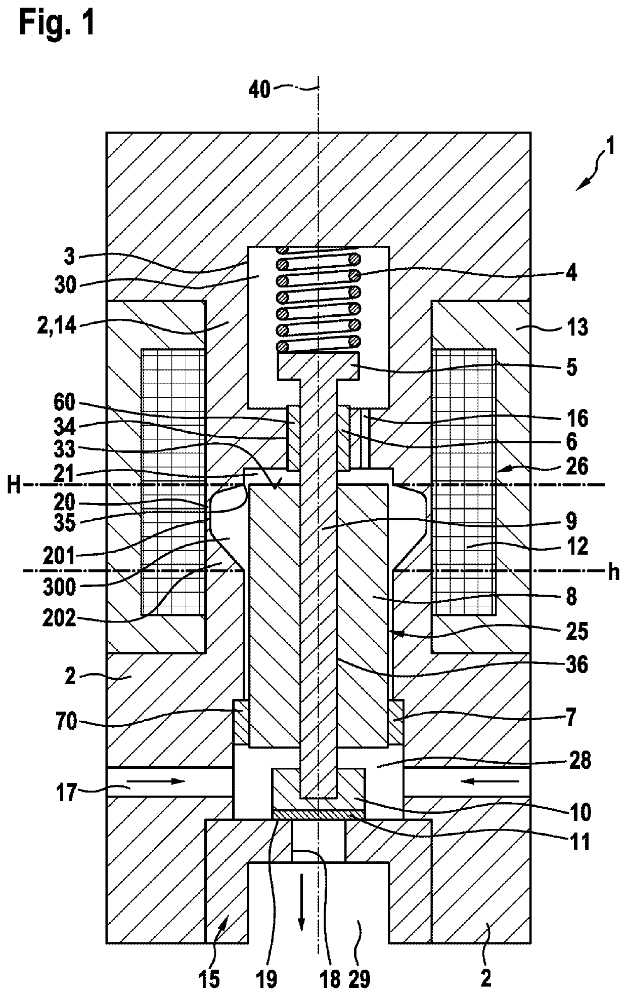
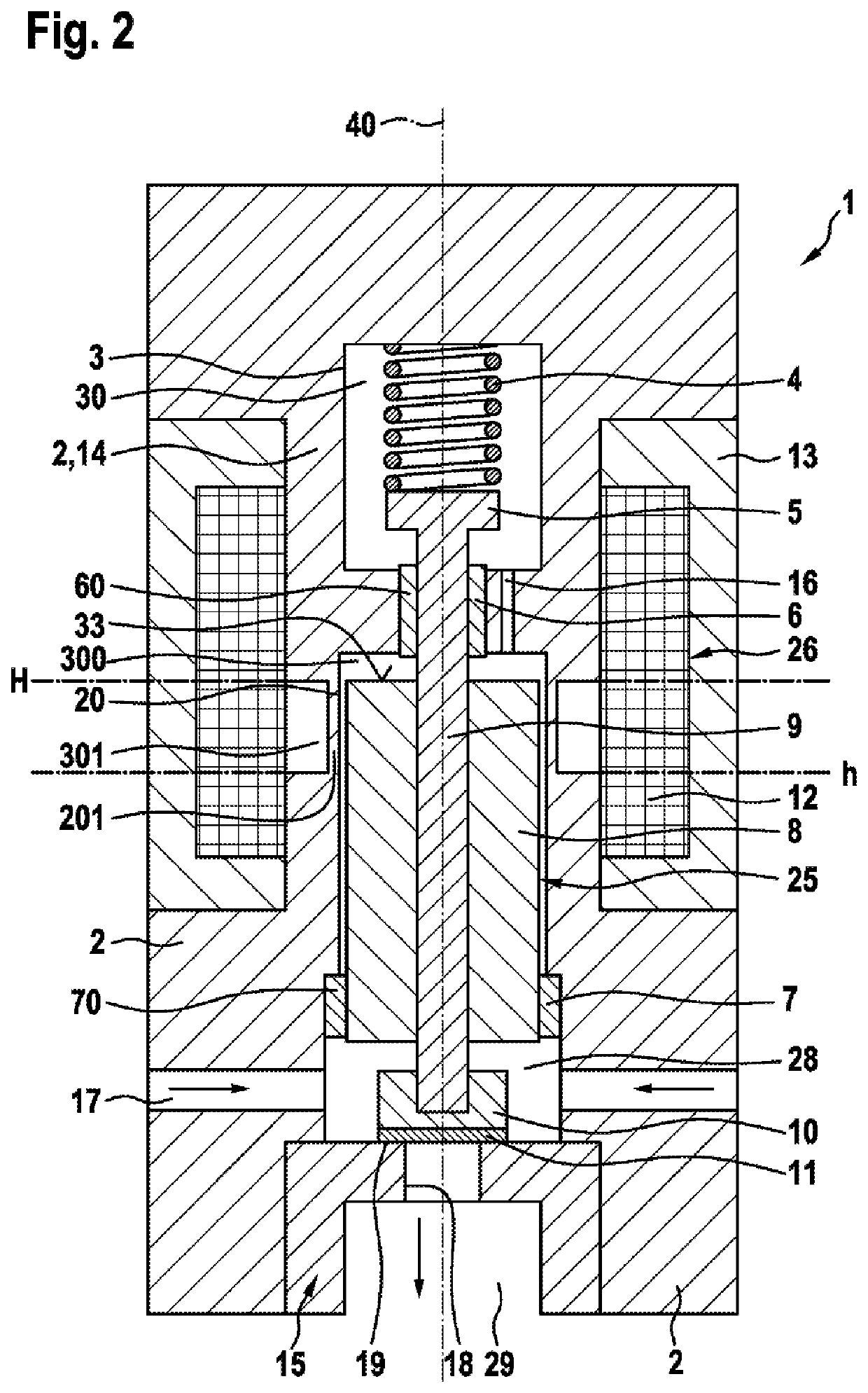
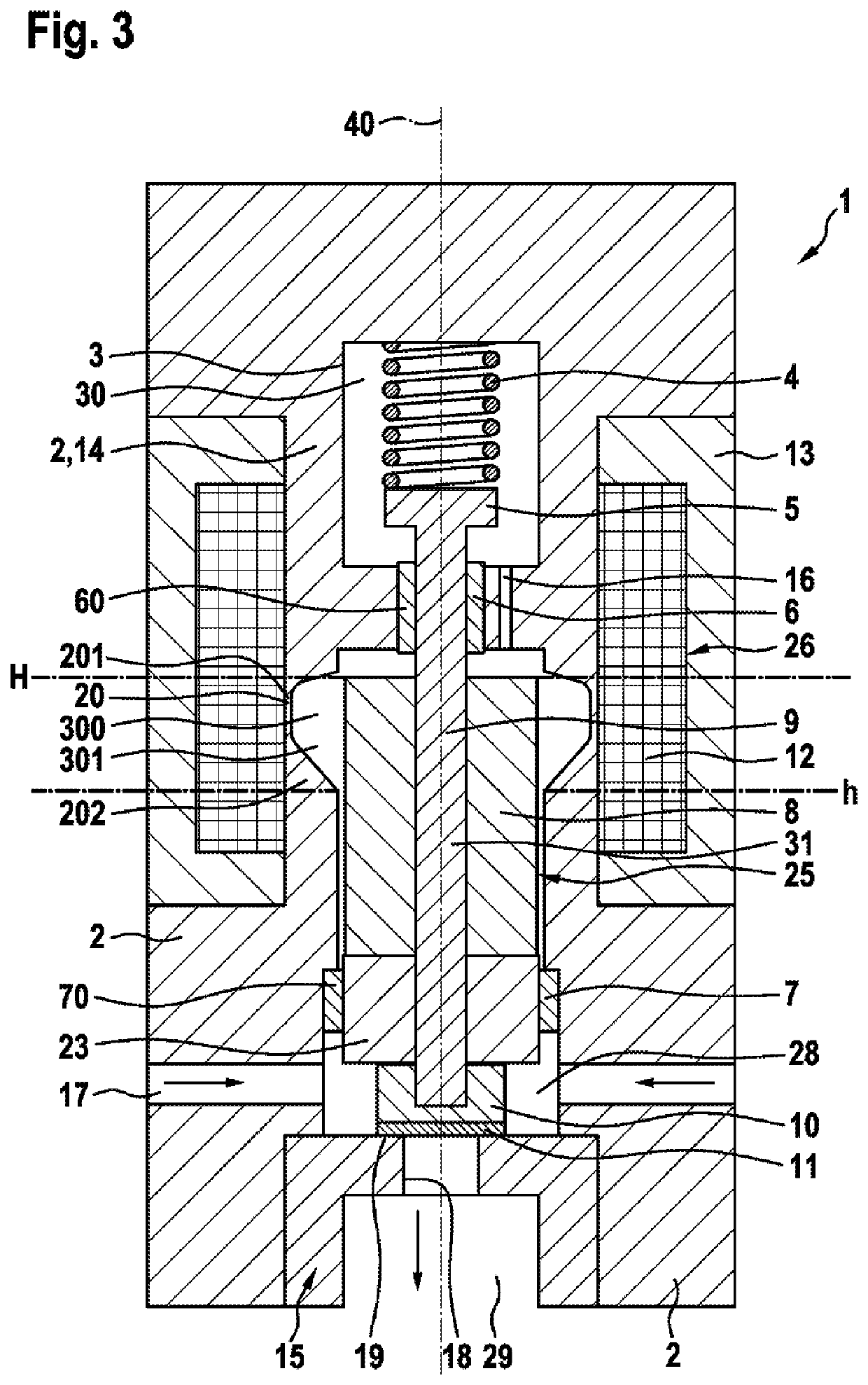
[0020]FIG. 1 shows a first exemplary embodiment of a proportional valve 1 according to the invention in longitudinal section. The proportional valve 1 has a valve housing 2 with an interior space 3. An electromagnet 26 which comprises a magnet coil 12, an inner pole 14 and an outer pole 13 is arranged in the interior space 3.

[0021]Furthermore, a magnet armature apparatus 25 which can be moved in a stroke movement is arranged in the interior space 3. The magnet armature apparatus 25 comprises a magnet armature 8 and a connecting element 9 which is received in a recess 36 of the magnet armature 8 and is therefore connected fixedly to the magnet armature 8, for example by way of a welded seam or by way of pressing. The magnet armature 8 is configured as a solenoid plunger and is received in the inner pole 14. The inner pole 14 has a recess 21 with a recess edge 35, into which recess 21 the magnet armature 8 dips during its stroke movement. An end face 33 of the magnet armature 8 lies a...


PUM


Abstract

The invention relates to a proportional valve (1) for controlling a gaseous medium, in particular hydrogen, comprising a valve housing (2), in which a closing element (10) arranged therein interacts with a valve seat (19) in order to open and close at least one passage opening (18). Furthermore, an armature device (25), which is operatively connected to the closing element (10), and an electromagnet (26) are provided, by means of which electromagnet a magnetic force can be produced on the armature device (25) and the armature device (25) can move reciprocatingly along a longitudinal axis (40) of the proportional valve (1). Moreover, the electromagnet (26) comprises an inner pole (14), an outer pole (13) and a solenoid coil (12) and the armature device (25) composes an armature (8). The valve housing (2) and the inner pole (14) are magnetically connected to each other by means of a magnetic choke point (20). The magnetic choke point (20) is formed in an axial region of extent of the armature (8). Furthermore, the inner pole (14) has a cavity (21) having a cavity edge (35). The armature (8) plunges in said cavity (21) during the reciprocating motion of said armature. In a closed position of the proportional valve (1), an end face (33) of the armature (8) lies at the same height as the cavity edge (35) of the cavity (21) with respect to the longitudinal axis (40), the cavity edge (35) forming the end of the magnetic choke point (20).

Description

BACKGROUND OF THE INVENTION[0001]The invention relates to a proportional valve for controlling a gaseous medium, in particular hydrogen, for example for use in vehicles having a fuel cell drive.[0002]DE 10 2012 204 565 A1 describes a proportional valve for controlling a gaseous medium, in particular hydrogen, the proportional valve comprising a valve body, a closing element and an elastic sealing element. At least one passage opening is configured in the valve opening, which passage opening can be released or closed by way of the closing element on a valve seat. Here, the elastic sealing element seals on the valve seat. The closing element can be moved in a stroke movement by means of a magnet armature by way of an electromagnet which comprises a magnet core and a magnet coil, and is loaded with force in the direction of the valve seat by way of a spring.[0003]Frequent opening and closing operations occur in the normal operating range of the proportional valve. To this end, a stroke...

Claims


Application Information

Patent Timeline
IPC IPC(8): F16K31/06H01F7/08H01F7/16H01F7/121H01M8/04089H01M8/04082
CPCF16K31/0655F16K31/0675H01F7/081H01F2007/086H01F7/121H01M8/04089H01M8/04201H01F7/1607H01F2007/085Y02E60/50
Inventor MAGEL, HANS-CHRISTOPHGRUENBERGER, ANDREASWURSTHORN, STEPHAN
Owner ROBERT BOSCH GMBH
Learn More