Control system and method for a vehicle system

a vehicle system and control system technology, applied in the direction of locomotives, transportation and packaging, signalling indicators on vehicles, etc., can solve the problems of not achieving the goals of a desired trip plan, significant challenges, and the amount of charge provided, and achieve the effect of engine efficiency

Pending Publication Date: 2021-02-04
GE GLOBAL SOURCING LLC
View PDF5 Cites 2 Cited by
  • Summary
  • Abstract
  • Description
  • Claims
  • Application Information

AI Technical Summary

Benefits of technology

The patent describes a method and system for controlling the use of an engine and energy storage device in a vehicle system to achieve specific objectives during a trip. The system determines the optimal engine and energy storage device settings based on their respective operational parameters and the goals of the trip. This can include when to charge or discharge the battery, and how efficiently to use the engine to achieve the goals. The technical effect of this patent is to improve the efficiency and effectiveness of vehicle systems during trips, by optimizing the use of both the engine and energy storage device based on their respective parameters and the goals of the trip.

Problems solved by technology

Similarly, the amount of charge provided, including the time spent recharging a battery directly impacts the amount of time a vehicle is on a trip.
However, depending on different variables associated with the trip, using greedy algorithms may not result in the goals of a desired trip plan.
In addition to this efficiency advantage, adding batteries can also offer benefits to reduce emissions (e.g. zero emissions in green zones), or improve throughput by utilizing batteries for faster travel times. With these opportunities, significant challenges exist due to the impact of charge and discharge condition on battery life due to capacity fade.
The capacity fade, combined with the high battery replacement cost, has made hybrid vehicles a less viable option than traditional vehicles.

Method used


Image

  • Control system and method for a vehicle system
  • Control system and method for a vehicle system
  • Control system and method for a vehicle system

Examples


Embodiment Construction

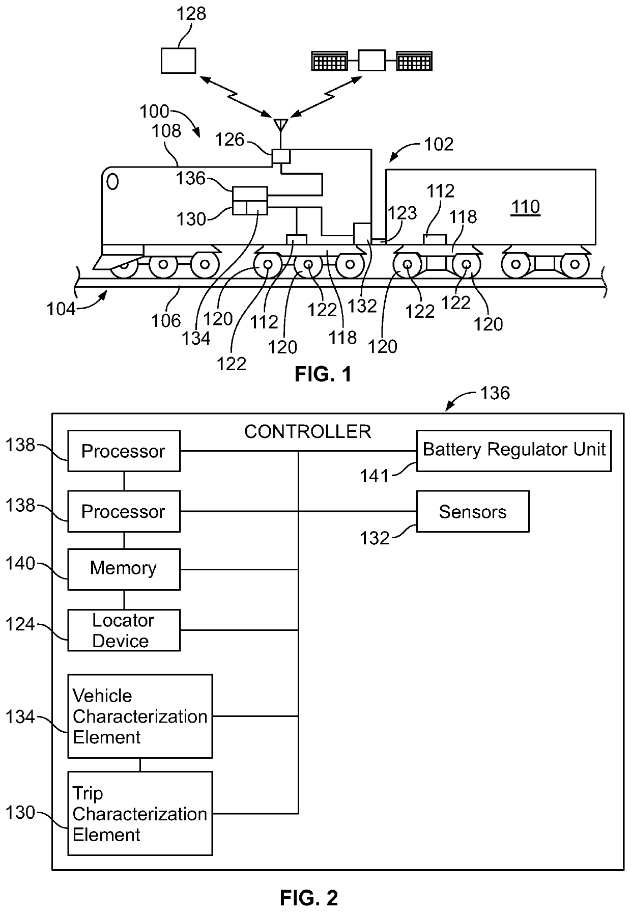
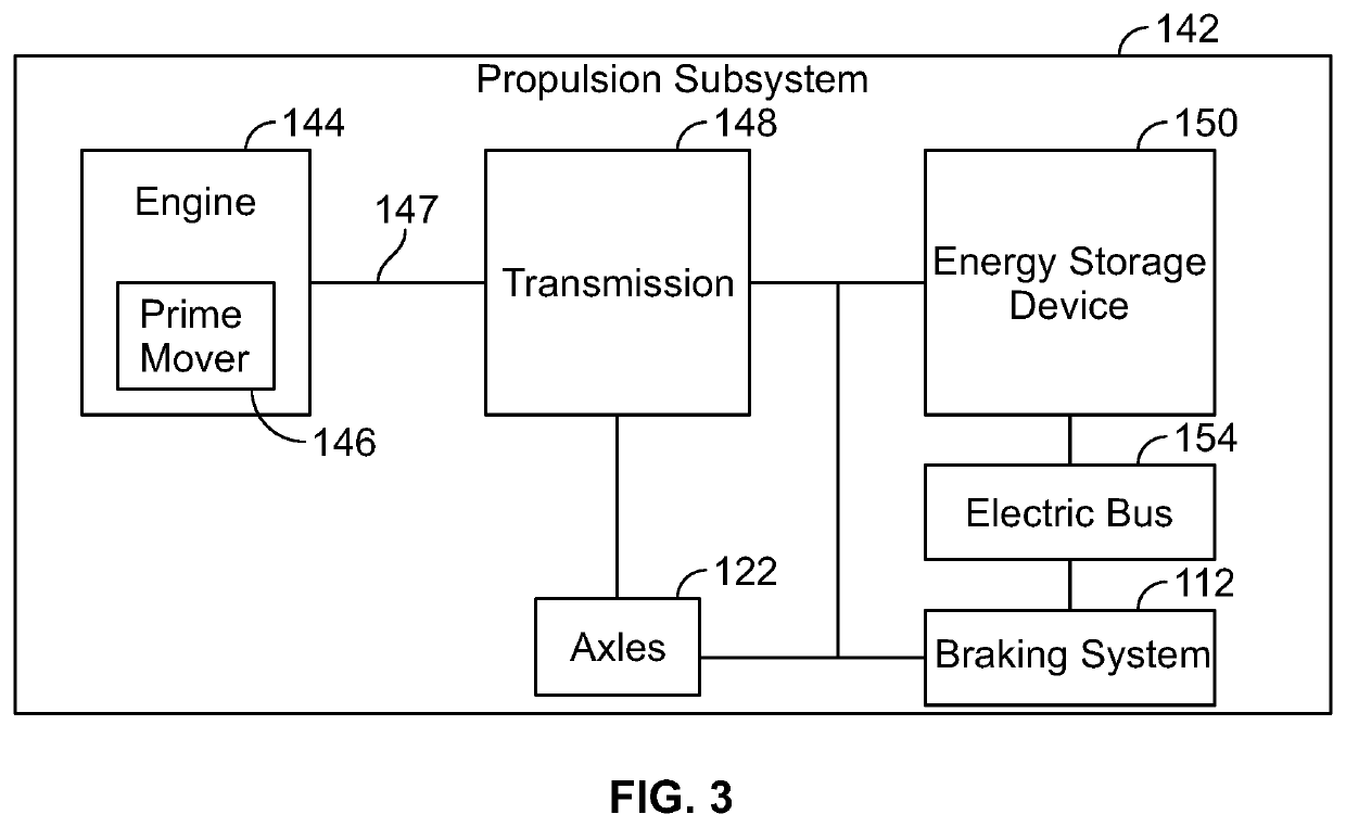
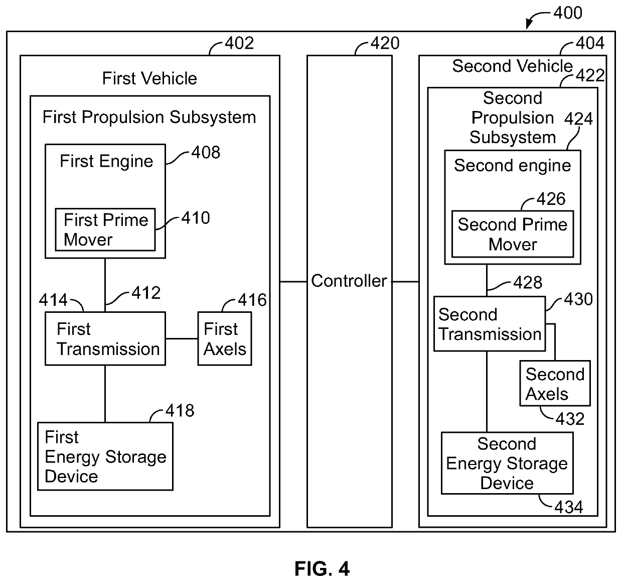
[0028]Embodiments of the subject matter described herein relate to a hybrid propulsion-generating vehicle that includes a control system that manages the power flows between an engine and battery of the vehicle. The control system enhances fuel savings of the engine by managing the flow, while alleviating degradation of the battery by operating the battery under determined charge / discharge conditions. In one example, the energy management of the control system may leverage railroad specific features such as the availability of track and trip plan information. The control system also solves a multi objective optimization problem that reduces a weighted sum of fuel and battery degradation over the trip to determine the engine and battery power forecasts for a given trip. To do so, a battery life model along with reduced order battery thermal model may be utilized to predict the battery degradation. This enables making optimal decisions that can simultaneously increase battery life and...


PUM


Abstract

A system and method generate a trip plan for a trip of a vehicle system along a route. The usage of an engine during the trip is determined based on engine operational parameters, energy storage device operational parameters, and one or more objectives of the trip desired to be achieved. The usage of the energy storage device during the trip is also determined based on the engine operational parameters, the energy storage device operational parameters, and the one or more objective, including when to charge or discharge the energy storage device during the trip.

Description

CROSS REFERENCE TO RELATED APPLICATIONS[0001]This application claims priority to U.S. Provisional Patent Application No. 62 / 880,926, entitled SYSTEM AND METHOD FOR CONTROLLING A VEHICLE SYSTEM TO ACHIEVE OBJECTIVES DURING A TRIP, which was filed on 31 Jul. 2019, and the entire disclosure of which is incorporated herein by reference.BACKGROUNDTechnical Field[0002]Embodiments of the subject matter described herein relate to controlling movement of a vehicle system.Discussion of Art[0003]Vehicle systems that travel on routes may travel according to defined trips from starting or departure locations to destination or arrival locations. Each trip may extend along the route for long distances, and the trip may include one or more designated stops along the trip prior to reaching the arrival location. These designated stops may be for a crew change, refueling, picking up or dropping off passengers and / or cargo, and the like. Some vehicle systems travel according to trip plans that provide ...

Claims


Application Information

Patent Timeline
Patent Type & Authority Applications(United States)
IPC IPC(8): B61L3/00B61L25/02B61C7/04
CPCB61L3/006B61L3/008B61L15/0081B61C7/04B61L25/025Y02T30/00B61C17/12B61L15/0062B61L15/0058
Inventor BROOKS, JAMES D.SEENUMANI, GAYATHRIMATHEWS, JR., HARRY KIRKNICHOLS, JASON M.
Owner GE GLOBAL SOURCING LLC
Why Eureka
Try Eureka